Started: 10/08/2000
Finished: 10/11/2000
Total Time: 7.5 hours
Total Cost: US$104.99 (+ my labor)
I must acknowledge the useful articles I pulled from the S2000 fans web site (both domestic and UK versions) on cracking open the interior, replacing the speakers, and swapping out the stock head unit. If it were not for these instructions and images, I may have given up (find out why later). Some of the following instructions, such as how to remove the panels, are based upon those articles and have been extended as I saw fit. My thanks goes out to 'Colin', 'WayneI', and 'Paul(UK)'.
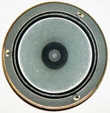
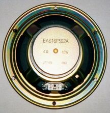
As you can clearly see, the stock speaker is nothing to speak of (HAH! That was punny). It's a simple 1.5-way (a paper cone with a cheezy whizzer cone), and at a whoppin' 15 Watts, this poor thing doesn't have enough punch to get out of a wet paper sack. So, in comes the replacement! I spent several weeks researching information on different speakers...power level, sensitivity, and most importantly, size. Sorry guys, size DOES matter.
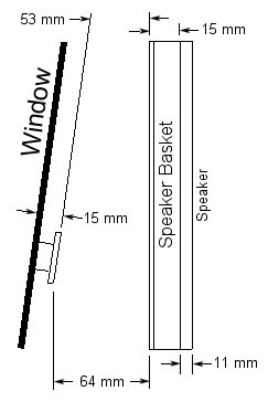
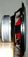
The largest problem S2000 owner's will encounter with speaker upgrades is finding a set that doesn't stick out too far in either direction. Too deep of a cone/magnet combo and the window can't roll down. Too high of a tweeter stack and you hit the door panel's speaker grill. There is a large selection of 2-ways that will fit, but the generally larger tweeter stack on 3-ways (and several 2-ways, for that matter) severely limit the choices. For those of you daring enough to modify/replace the speaker basket, here are some measurements that will help you decide what will fit (note the smaller clearance near the top of the basket...the window is angled). The space between the speaker basket and the window is obviously where the speaker magnet goes.
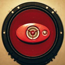
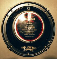
What did I decide upon? The cool looking Sony xs-V1631 Xplod 3-ways. While everyone has been putting easy-to-find 2-ways in, I decided the extra brightness and depth of a 3-way was too good to pass up. The specs are decent enough:
You can also try Sony xs-V1621 3-ways. They can only handle 130W max. and the lower frequency range is 35 Hz, but the sensitivity is up to 91 dB. But for US$20 difference, I think you can tell what I want.
And please, don't send email telling me how the speaker grill and the position of the speaker kills everything I gained by putting in a 3-way. The price difference was $20 to get a better midrange, more power handling capacity, and a wider frequency range. The other option was separates, but I'm not ready to go drilling holes in my car's interior. With this mod, I only need to buy a new speaker basket (the cut ones would still work) and pop the stock speakers back in should I decide to make it 'factory fresh'. And I still have the 'door protector' (hey, that's what Honda labeled it), a decent-sized pocket at the rear of the door, to fill up with whatever.
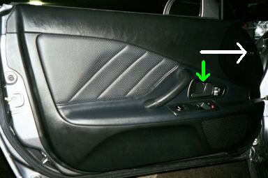
Here's an image of the stock interior panel of the door. This is what it looks like before, and hopefully after, my modifications are finished.

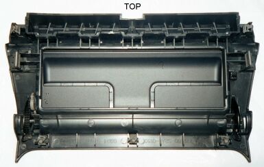
This is what the inside of the panel looks like. Refer to these pictures for the following instructions on how to remove the panel.
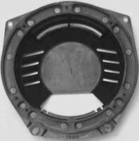
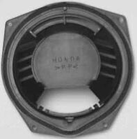
Here are some images of the speaker basket (copied from the UK site because I forgot to photograph mine before slicing
into them
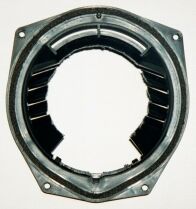
The back of the speaker basket had to be cut out for the new speaker, but I wanted to leave as much there as possible for protection against water. The plastic is actually quite soft, so I took a coping saw to them. For these particular speakers the magnet fits snugly if you cut just around the outside of the lip of the back flat piece (80mm diameter). Unless you plan on bending the speaker connections away from the speaker, you will also have to cut away a small piece of the lower portion where the original wires were connected. This, of course, leaves the magnet open to water dripping from the window. To combat the elements, I glued a piece of plastic bag (you could also use visqueen) to the rear of the basket. This still leaves the sides and bottom open to the air through the vents on the stock basket.
The connector for the stock speaker is annoyingly tight (now THIS I expected), but I was truly stunned at the thin wire Honda chose to use. So thin, in fact, that I thought they had figured out a way to use copper vapor instead of solid wire ;)
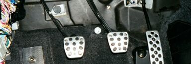
So, now we come to the toughest part of the job...wiring! If you are easily frustrated, have a weak heart, or a bad back, this is NOT a job for you. Let a professional do it...you know, some pimply-faced 16-year old who can fit his body into a 4 cubic foot area with pedals without getting bruised and beaten.
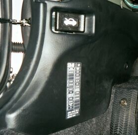
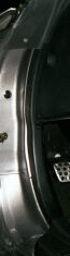
We have to remove this panel to get to the wiring block and the conduit between the car body and door.
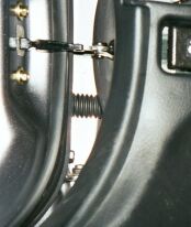

The really tough part is getting the new wire through that conduit. I can assure you that Honda did not leave a lot of breathing room for their wires, so squeezing the new one in is an adventure in patience. I used a snake (read coathanger). The wire needs to be thin enough to get in that tight spot and be pliable, but not so thin that it bends at the slightest push. Many thanks to g-s2k who suggested (too late for me, damnit) using an industrial length zip tie! I'll be darned if that isn't the coolest idea...it bends to the contours easily and won't puncture the rubber booties in the door jamb. The following directions discuss using the coathanger since that was what I had at the time.
Once the wire is in, what you do with it is up to you. Honda uses several connector blocks along the wire's path. Personally, I thought it would be too much of a pain to rewire each one, so I snaked it between the wiring blocks and around the front of the firewall under the carpet. I must admit, once I had the process down and the fish bent to the correct radius, the passenger-side door only took me about 10 minutes to complete.
Pop the new speakers into the basket using the same mounting screws and holes, put the door panels back on and you're ready to connect the wires to the radio. For instructions on how to remove the head unit, see my partial instructions under "Head Unit Upgrade".
The head unit connector is simple enough to get off, but replacing any wires in it is NOT! Many people have created a patch cable by using a new connector from Honda. But I'm an engineer, I can figure it out, right? WRONG! I dinked with that damn connector for nearly 45 minutes and the best I could do was beat it up.

(My apologies for the poor quality/out of focus pictures) While I admit I like the design of the connector from an engineering standpoint (it's pretty solid once snapped together), I have to hate it from a tinkerer's standpoint. Once I figured out how to get the cap off of the top and bottom, I tried to yank the wires out with no luck. There is usually a small spike on the metal connector attached to the wire that prevents you from removing it once it has been snapped into the connector. Well folks, it did it's job! I never did get those old speaker wires out of there (which I suppose is for the better). I ended up shoving the new wires down behind each of the old wires and snapping the casing closed. If I ever go back to stock speakers (sell Michelle?!) I can just plug them back in...no need to get back into the stereo compartment. To be honest, I was so drained from working on this project, I just wanted to get it finished (luckily you can't see where I became hurried).
After slapping everything back together, I cranked her up and christened my new speakers with a few passages from Rush's Power Windows CD. There was a slight increase in available volume, and certainly a sharper/brighter image. A job well done, if I do say so myself. Michelle agrees :)
Started: 04/04/2001
Finished: 04/04/2001
Total Time: 2.5 hours
Total Cost: US$280.00 (+ my labor)
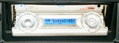
While the stock head unit certainly sounds better with a higher quality speaker set, it is still lacking in certain refinements (like a clock?). I installed a Sony CDX-M750 head unit to give my ears that extra little sparkle, and after dealing with a few small issues, I must say it's an impressive unit. For all intents and purposes, the unit is a drop-in replacement for the stock stereo (other than the electrical connector), but for that true quality install look, you'll need to cut a simple flat faceplate.
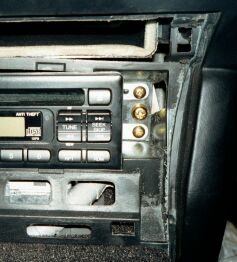
Here are some instructions on how to remove the stock radio. Remember, we're working close to leather and other easily scratchable surfaces, so be careful with the pointed edges.
PICS COMING SOON! (message left on 04/07/2001)
The metal brackets on the side of the stock unit are a near direct fit to the Sony unit...I say near because the hole in front of the rear screw needs to be slightly enlarged towards the rear of the radio. Why? The bracket has a small dimple facing towards the radio...unfortunately, this dimple doesn't quite line up with the hole on the Sony unit (you could always remove the dimple from the bracket). This took me 10 minutes with the dremel tool (or use a good file).
As you can see, there is a gap around the faceplate. about 80% of this gap is taken up by the faceplate (when installed) and looks reasonable...but for a professional install, a piece of plastic should be cut to cover the gap from behind.
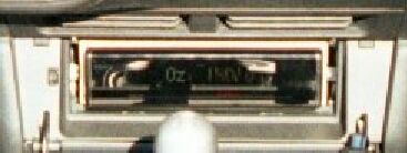
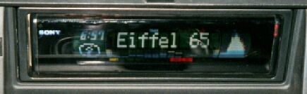
So, without further ado, here are some pics at night with the faceplate in the up and down positions.
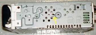
For those daring enough to try such an install (it's really easy, unless you have two left thumbs), here is a pinout list and color code for each wire on the stock connector. The pins match up with the list when held in the manner shown in the picture.

| Pin | Function | Color | Pin | Function | Color |
|---|---|---|---|---|---|
| 1 | Antenna/Remote Amp Relay | Yellow/Green | 11 | N.C. | - |
| 2 | 12V Accessory Power | White/Red | 12 | N.C. | - |
| 3 | Dash Remote | Green/Red | 13 | N.C. | - |
| 4 | N.C. | - | 14 | Mute | Yellow/Blue |
| 5 | Right Rear Speaker + | - | 15 | Right Rear Speaker - | - |
| 6 | Left Rear Speaker + | - | 16 | Left Rear Speaker - | - |
| 7 | Right Front Speaker + | Green/Black | 17 | Right Front Speaker - | Light Green |
| 8 | Left Front Speaker + | Green/Yellow | 18 | Left Front Speaker - | Gray/Red |
| 9 | Illumination Signal | Red/Black | 19 | N.C. | - |
| 10 | 12V Memory Backup Power | White/Blue | 20 | Ground (chassis) | Black |
Started: 04/30/2001
Finished: 04/30/2001
Total Time: 30 minutes
Total Cost: US$42.75 (+ my labor)
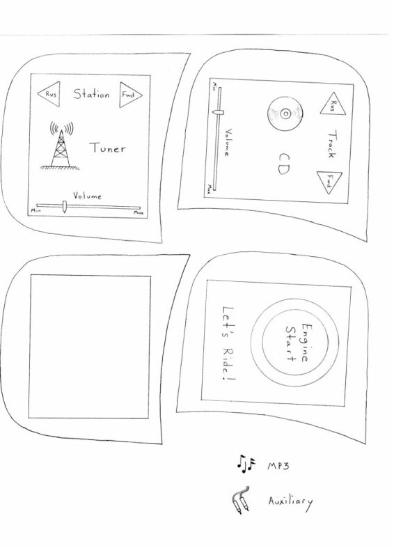
With the replacement of the stock head unit comes the loss of the dash controls. When I get a free week or two (HAH!) I'll be designing a patch-through device that will allow me to not only keep the controls, but to modify their functionality as well. I have already done some preliminary work on a color touch-screen LCD unit which has been met with mixed emotions. My intent was to replace the left panel (and eventually the right, as well) with the LCD as a drop-in replacement. This would involve replacing the start button with a touch-screen graphic of one, which seemed to hit a nasty chord with most folks. There were a number of people who loved the idea, but I suppose the only way to truly guage interest is to build it and see. Here's a link to the sketches I drew for some of the different screens it would display.
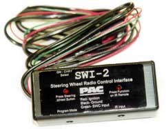
But until then, there's a nice little toy from a company called Pacific Accessory Corporation. This little treasure transmits (after programming, a very simple thing to do) infrared commands (learned from your new head unit's remote) through an IR LED that you stick somewhere near the stereo. Thanks to Sunny_P, the cheapest price I have is at Wholesale Audio ($59.95). The pic shows the SWI-2, but the one we want is the SWI-3. If you want to play yourself off as an installer, you can get it for $38/each (or $32/each for ten) from HP Distributing (1-800-395-2927)...thanks LATEOTT!
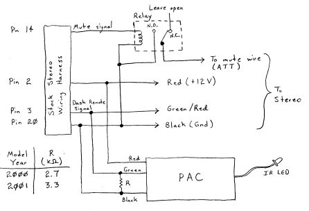
The S2000 has a semi-unique mute button manner of operation (it supplies 12V when pushed instead of a reference to ground), but don't worry about losing functionality...a fix is simple enough. Connect a 2.7kohm (for MY2000) or a 3.3kohm (for MY2001) resistor between the PAC's Steering Wheel Control wire (green) and ground wire (black). Since the S2000 mute button suppplies +12V (and most stereos require ground at their mute input to activate the mute function), a relay must be used. This is separate from the PAC unit, and can actually be used by itself if all you want is a quick and dirty on/off switch for the audio residing on the dash. The +12V output from the mute button connects to one side of the relay coil with ground on the other. When the coil is energized (i.e., the mute button is pressed), the relay switch should connect the stereo's cellphone mute input to ground (when not energized, the input is left floating, i.e., not connected to anything, as it normally is when you don't have a cellphone).
Programming is extremely simple: Press the program button (PAC LED turns on), then press the stock control you wish to program until the LED goes off. Release the stock button and press the new head unit's remote button that corresponds to the desired functionality, again until LED turns off. Do that for each function and you're ready to rock!
Several issues have popped up concerning this unit, so I hope I remember to address them all (let me know if I forgot something). First off, the tolerance on the S2000 dash control resistances is pretty large. What does this mean to you? Well, it means the two resistances mentioned above may not work for you, but have no fear, there IS a solution. You have the option of either using a different resistor on the outside (usually a higher resistance is needed), or go the route I took and replace one of the resistors inside the PAC unit (in which case the external resistor is unneccesary). Go here for pics and instructions on what resistor to replace and with what if you go the second route. There are several possible symptoms, but the most common is the unit won't program correctly - the programming LED comes on for a second, then everything goes dead until power is reset.
Another problem, which generally only shows up when receiving a pre-programmed module, is certain buttons work erratically, or won't work at all. Again, this is due to bad tolerancing on the dash control resistances, but is easily solved by reprogramming the PAC unit using the dash controls which will be used with that particular PAC unit.
Started: 04/07/2001
Finished: 04/07/2001
Total Time: 2 hours
Total Cost: US$39.07 (+ my labor)
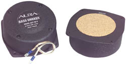
While 6 1/2" speakers put out a surprising amount of bass, they still lack that bass "feel". Aura has created an item that helps to give the impression of bass without the need for large boxes and power-hungry woofers. How do they accomplish this, you ask? For all intents and purposes, it's nothing more than an off-center weight on a motor, and since low bass (lets' say sub-20Hz to 100Hz) is generally felt and not heard, these accomplish the goal quite well.
Aura suggests attaching the bass shaker units to a portion of the frame that is near the seats and easily resonates (i.e., vibrates). However, in the case of the S2000, the simplest method is slapping them in the map pockets on the bottom portion of the seatbacks...no need for drilling into metal, plastic, or leather. The shakers only need about 25W RMS, and since the Sony head unit has rear outputs that aren't being used (19W RMS), it was a perfect match. Wiring is similar to that for the speakers, with the main chunk of the wiring running along the front firewall and along the side sills. The wires pop up out of the holes in the carpet underneath the seat and can either be run through a small hole in the bottom of the map pocket, or just left hanging and enter from the top (hey, who looks behind the seats?).
The sound...er, excuse me, the FEEL, is truly awesome. Power to the units can be adjusted by using the head unit's fader control, but at a 50/50 mix front to back, they feel just right. One of the great side benefits to this type of modification is that although it feels like you have a subwoofer in the trunk, there is no danger of losing your hearing (well, at least from these things) since they do not produce any actual sounds waves (and your back feels great from the massage).
Started: Not yet...
Finished: Not yet...
Total Time: ???
Total Cost: US$???.?? (+ my labor)
Even though the replacement head unit packs a lot more punch than the stock unit, 19W RMS still lacks a bit when cruising with the top down at 80 mph. No definite decisions have been made yet, but I'm currently looking into a Sony XM-1002HX (which has seemingly been discontinued and replaced by the XM-1502SX, which by Murphy's Law, is stronger, yet too large to fit under the seat). The trick on the amp is where to put it...some have placed it in the trunk in various places, but I'm partial to placing it under the driver's seat (the passenger side is too crowded with tranny bumps and such for anything larger than an amp of a few watts). I will continue my search and update as soon as possible.
Started: Not yet...
Finished: Not yet...
Total Time: ???
Total Cost: US$???.?? (+ my labor)
To round out the audio we definitely need some more bass (although with the bass shakers installed now, I don't feel extra bass is as necessary as before). I will most likely upgrade to an external amp, so that may spawn off a separate project. We'll see...