Digivac (VFD) Thermometer
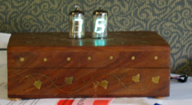
I picked up a bunch of Tung-Sol Digivac VFD tubes on an Ebay auction for a quite good price. I built a thermometer as an experiment in driving the VFDs, as it uses only two tubes. The case is a hand-inlaid jewelry box from India that I picked up from a street vendor for $10.00. The Digivacs are attractive VFDs, with a clear mica panel supporting the digit anodes. The components in the tube are large so you can easily see how the device is built and what is going on.
Driving a VFD tube is pretty easy once you figure out a few tricks. Most VFD tubes have an anode for each segment, a screen for the digit, and a filiment which acts as a cathode. The anode and the screen should be held to 20v – 30v to turn them on. The screen is used for multiplexing. Holding it to ground repels the electrons from the cathode so the segment won’t light up, holding it to the anode voltage attracts the electrons.
The hardest part to figure out for me was what to do with the filament. It should be held at a low voltage, but should carry a current. The suggested voltage seems the be in the 2.5V range. For large displays, the literature seems to suggest applying an AC waveform, as otherwise the voltage drop across the filament causes brightness variations. The lm9022 chip is designed to create such a waveform. Its cheap, and the data sheet provides the schematic for a simple RC oscillator circuit to drive it.
One consideration that I did not read about is the need to limit the current through the filament. Most filaments have a resistance of about 10 Ohms, and should carry about 50 ma. The lm9022 provides a waveform with an almost 5 volts drop. When I connected it to a digivac, I pumped .5A through the filament, which started glowing red and nearly destroyed the hard-to-find tube. I dug around the web some more until I came across a data sheet for the digivac, which specifies a current of 45ma. I put in a current limiting resistor, and it worked fine.
The digivac tubes do not have screens, so I used a direct drive for the anodes. Driver chips are readily available from Maxim and Allegro. The temperature sensor is a Dallas 1620, which is convenient though a little bit expensive. One problem with the chip thermometers is that the principal heat transfer path is through the wires into the package. I had planned to mount the chip on the back of the case, but I could only get accurate readings by pulling the chip out and exposing the connecting wires (which you can see to the right).
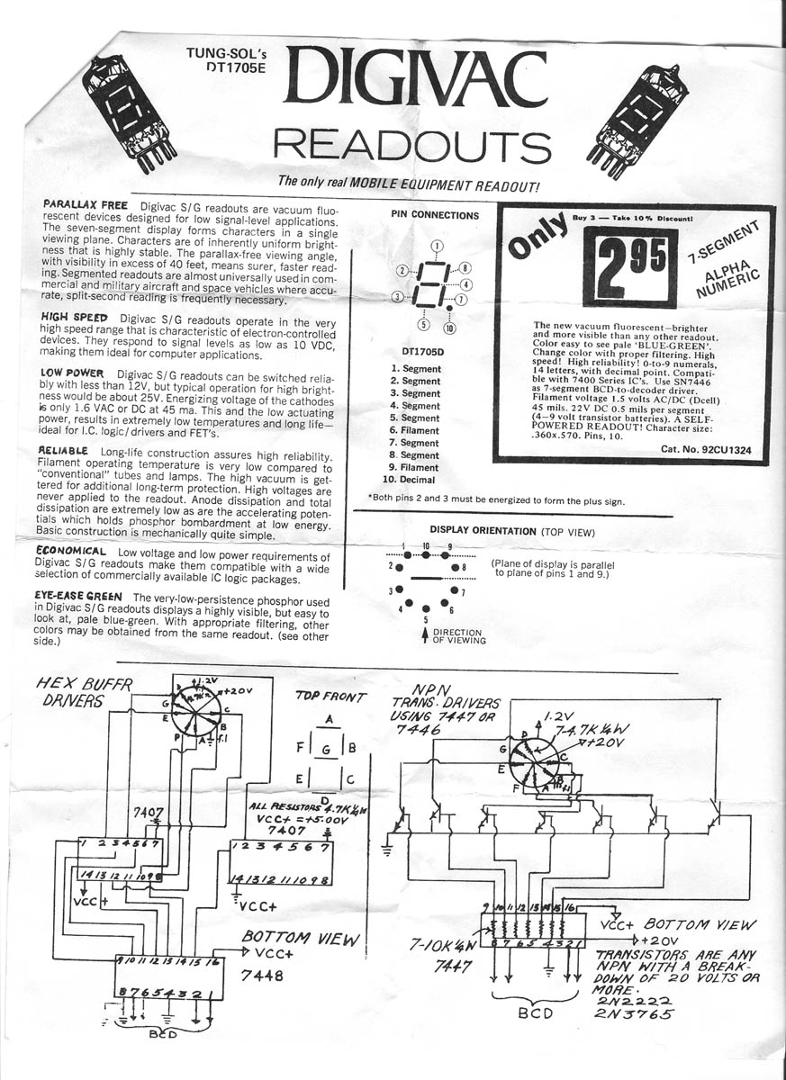
Below is a scan of a Digivac DT1705e display. The basic recommendations: 1.2 volt drop across the filaments, 20 volts on the anodes.