Nixie Clock
After building the spinning sign clocks, I found some web pages about nixie displays (search google for nixie). I find nixie displays very interesting for several reasons. For one, I remember these mysterious devices from visiting my parent’s labs when I was a child. Nixie tubes are relics from a time of technology transition, from analog to digital, from tube to solid state. They have an ironic nostalgia. Their warm neon glow, human-oriented calligraphy, and obsolete technology evoke a “simpler” time, but back in the day they represented the frightening approach of computerized, all-controlling modernism. And besides to drive them you need to generate potentially lethal voltages.
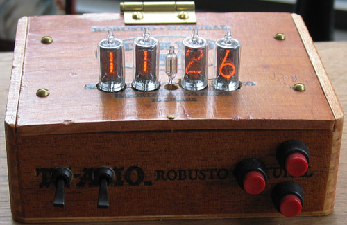
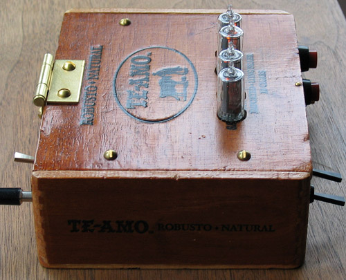
Below are pictures of my nixie clock, a front and a side view. I searched NYC flea markets until I found a beat-up cigar box, the better for ironic nostalgia. The tubes are Burroughs 5863SI’s.
I had never worked with high voltages before, so building the clock required a lot of research. The first problem is generating the 170+ volts for lighting the tubes (Nixies are not incandescent, they are neon gas discharge. Low power but they need a high voltage for ionization). The nixie clock articles that I read suggested using a transformer to step up line voltage. I had a couple reservations about that approach. First, I didn’t want to deal with bulky transformers. Second, I thought that I would probably kill myself by accidentally touching a wire.
Instead, I used the Maxim Max1771 step-up voltage regulator to generate 170 volts from 12. Its pretty easy to use, just follow the schematics in the documentation (a hint : if you are stepping up from 5 volts, be certain to use the IRLxxx logic-level MOSFETs. The chip can’t drive regular MOSFETs from 5 volts). The circuit is small, can be driven from a wall wart, and is safe: isolated from line voltage and current-limited.
I wanted to multiplex the tubes (to reduce the amount of wiring work), which means I need an anode driver. The simplest method I found was in an article by Jason Harper : use a high-voltage optoisolator such as the Toshiba TLP627. Simple, cheap, and reliable.
Next I needed cathode drivers. I’d read so much about using 7441 TTL chips that I tracked down and purchased a set. In my opinion, it was a mistake. The Burroughs 5863SI has two decimal points, which I use to indicate that the time is being set. I drove those with Allegro UCN5842’s. These are cheaper than 7441’s, have 80 volt breakdown (as opposed to 50v for the 7441), and are loaded via a chainable serial interface. The 80v breakdown means that you can do digit blanking. I had a big problem with ghosting from the multiplexing. The tubes have a bit of “capacitance” and you need to turn off the cathode a little bit before you turn off the anode. Easy with the 5842s, impossible with the 7441s. I eventually found a multiplex frequency which gave a good compromise between flicker and ghosting.
The final touch is a ISD1110 voice recorder chip. This chip can record about 20 seconds of lo-fi sound. I use it to record a ding-dong bell sound (I hit a pair of glasses with a spoon to get the sound). I play the ding part on the quarter hour, and the ding-dong on the hour. The switch in the back of the clock turns the chime on and off. The chime is actually quite charming and useful.
The source code is here.