Spinning Sign
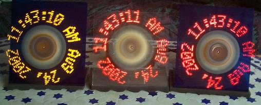
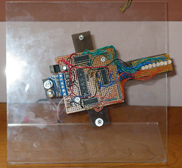
I wrote an article about how to build a “spinning sign”, you can read it at the Seattle Robotics Society. I fiddled around with the idea until I managed to make the clocks in the above picture. In brief, the image is created by spinning a wand of 8 LEDs at 20 RPS. That way I can make the 8 LEDs do the work of 1200 (150 columns). The signs are really serial terminals. The actual clock connects to the spinning sign (through the shaft) and emits a new message five times a second. The ideas in the article pretty much just worked, although I have learned a few more things:
- I can get reliable communications at 9600 baud, as long as the sign is very well balanced.
- The clock box emits a message five times a second, so that glitched messages disappear quickly. I should have also used a checksum to avoid displaying the glitches in the first place.
- The design in the article uses an elaborate mechanism involving an optoisolator to detect the timing signal and an RC network to reject glitches. A much better approach is to sense when the timing signal is pulled to ground (protected with a diode), and do glitch rejection in software.
I used three-color LEDs (from superbrightleds.com) to build a full color sign. It displays the 8 basic colors well, but my attempts at greyscale just flickered. I haven’t figured out a creative use for it yet. In the picture below, note the balance weights (screws and washers) on the bumps on the square.