Panaplex Calculator (V1)
I decided that it would be fun and challenging to build a calculator out of vintage components. For one, vintage calculators are the source of a lot of vintage components. A major stumbling block was a source of keyboards. Older calculators have much better keyboards than modern calculators – large keys and positive feedback including a satisfying click (modern keyboards generally use conductive membranes, which are much cheaper and perhaps more reliable but really not as tactilely satisfying).
While scanning ebay, I found the treasure I was looking for: five burned-out calculator circuit boards, three with keyboards and four with panaplex displays. I had the parts I needed, it was just a matter of putting it all together.
This project wound up being much more difficult that I’d at first anticipated. The first issue was to decode the calculator keyboard, which in turn was on the same circuit board as the (defunct) processor. I cut away the keyboard and decoded the keys. The keyboard required a surprisingly large number of pins (12), so I dedicated an AVR to keyboard decoding, producing ASCII interpretation on its USART.
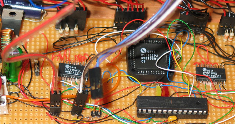
Next, I built a circuit board to drive one of the panaplex displays that I’d extracted. Panaplex generates light by the high voltage (170+ v) ionization of Neon, so I used specialized high-voltage chips from Supertex: the HV513 for the anode driver and the HV5122 for the cathode driver (the HV5122 uses +12V positive power, but can be driven by the +5V signals from the AVR microcontroller). I built a 180V power supply using the MAX1771 chip. Unfortunately, my design, or build quality, or both, was not good enough. The HV power supply eventually became unstable swinging up to 350+ volts. These swings destroyed all the chips in my circuit, requiring that I replace them. At this point I realized that I could purchase a HV power supply kit for only a little more than the cost (to me) in parts. The kit is from AllSpectrum, http://www.allspectrum.com/store/product_info.php?products_id=521 . With the added cost of destroyed parts, I think its cheaper to buy the kit than to make it myself – the argument that convinced my cheapskate self.
I rebuilt the circuits and then faced the next issue: how to program it. I had assumed that my C programming language came with double-precision floating point arithmetic. It doesn’t, just single-precision. Single-precision float is not precise enough for an 11-digit display. I searched for an AVR C compiler with double precision floats, but came away frustrated (GCC/AVR might have it but I had (have) other issue with GCC). So, I decided to write my own extended-precision arithmetic package. Doing so took a while, the code is here.
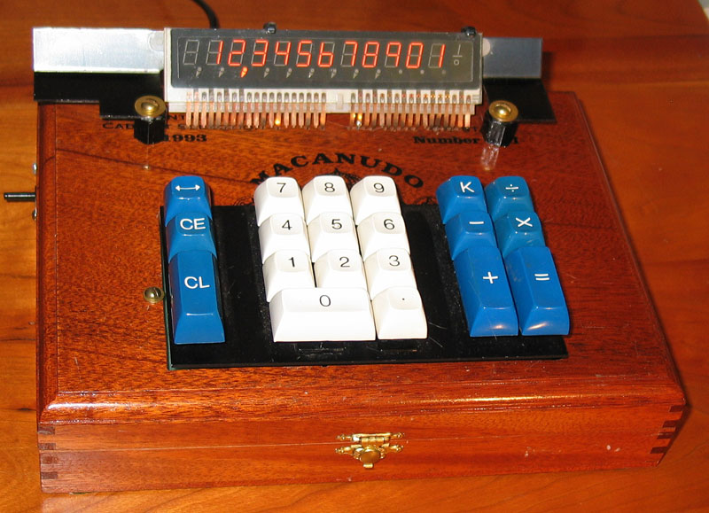
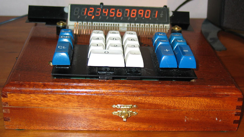
The end result is packaged in a cigar box, here is a frontal view
The Supertex drivers come in non-DIP packages, the HV513 in SOIC and the HV522 in PLCC. While PLCC sockets are cheap and easy to find, large SOIC sockets or breakout boards are not. I decided to take the approach of Elm-Chan : solder directly to the surface-mount device. I’m not nearly at Elm-Chan’s skill level (see his exposition here), but I’m getting better. I use Kynar wire-wrap wire for the Supertex parts and have had no problems with insulation breakdown.