Relay Clock (Nixie)
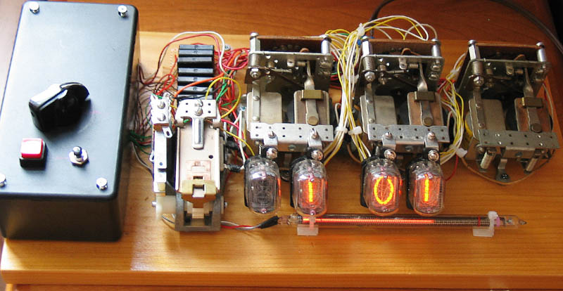
For this clock, I use stepper relays to drive the nixies. The right three relays are 27-pole, single toggle, while the relay on the left is double-pole, single toggle. The 27-pole relays use a ratchet mechanism to step from one position to the next when its right solenoid is pulsed. The left solenoid resets it. I managed to find a set of these relays for a low price from an electronic surplus web store. The 27-pole stepper relays were used and had a lot of black gunk on their contacts, which I had to clean off before the relays would work.
I use IN12 nixie tubes; their sockets are readily available and it turns out that they fit very nicely when attached to the screw holes on the front of the 27-pole relays. The glowing bar in front is an IN-13 linear indicator tube. I use it as a seconds indicator -- on each tick the glowing part becomes slightly but noticibly longer. I use Jeff Malin's circuit to drive the tube, except that I use the PWM provided by the ATMega8 as the digital-to-analog converter.
The black box on the left contains the power supplies and the microcontroller -- an ATmega8. The black rectangles behind the 2-pole relay are solid-state relays. I use them to convert logic level pulses from the ATMega8 to the 120 VAC power needed to drive the stepper relays.
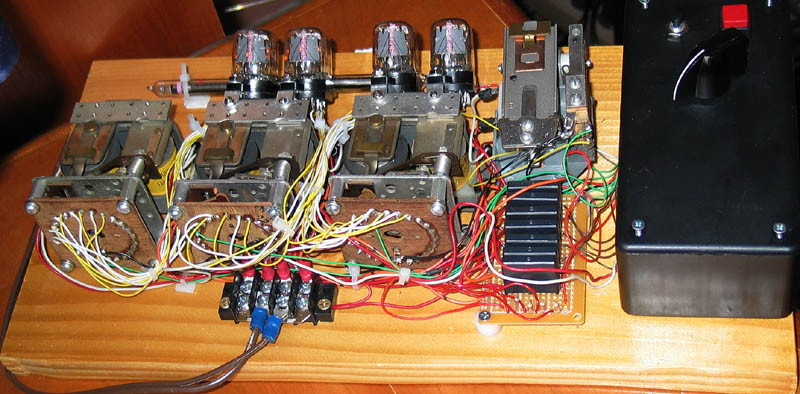
From the back you can see the circular array of relay contacts. The logic for driving the relays is quite simple. Once a minute, pulse the 1-minute forwarding solenoid. If the pulse moves the relay past the '9' position, reset the 1-minute relay and pulse the 10-minute relay forwards. The handling of the other digits is similar. I detect when the 1-minute relay has ratcheted past the '9' position by a wire attached to the 11th contact of the relay (the green wire) and detecting when this line is pulled to ground. Again, the other relays are handled similarly For the 1-hour relay, I need to detect when the relay is at the '3' position (to change from 12 to 1). Since this line is a nixie cathode line, I need to protect it with a diode to avoid blowing out the microcontroller (as it will be driven to about 60 volts). If more than one solenoid needs to be activated when the 1-minute changes, they fire off in sequence. Its fun to watch, especially at 12:59.
To set the time, use the knob to select hours, minutes in increments of one, or minutes in increments of 10. Then pressing the red button activates the forward solenoid on the appropriate relay. If you move past the end of the valid numbers, I reset the relay, but I do not propagate a pulse to the next relay. The small black button resets the seconds.
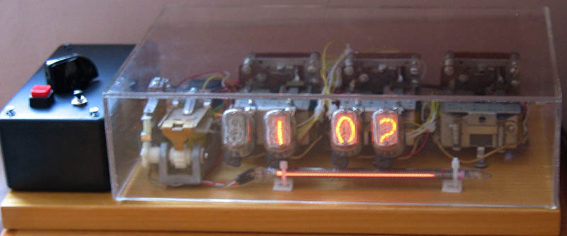
I had a plastic cover made for the clock, the above is a blurry photo of it. I felt that I needed to keep the dust out of the mechanisms. Also, the relays have a pretty loud click, which I was hoping the cover would muffle. But it doesn't. I also used shock-absorbing mounts to attach the relays to the board to avoid amplifying the sound. I think it helps a little. Another good reason for the cover is that there are exposed high voltage wires and I didn't want the cleaning staff at my office to electrocute themselves and then sue me.