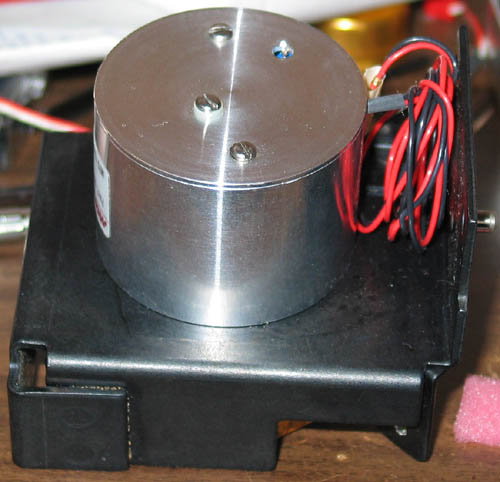
I managed to pick up some interesting laser scanner motors for a low price on ebay. They are 12-sized mirrors mounted on a regulated 3-phase motor. Each mirror is at a slightly different angle. If one attaches a laser to the mounting point (visible in the photo below), the result is 12 scan lines.
The picture below is the bottom of the motor. The hole in the bottom allows access to a potentiometer which adjust the rotation speed (about 30 rps).
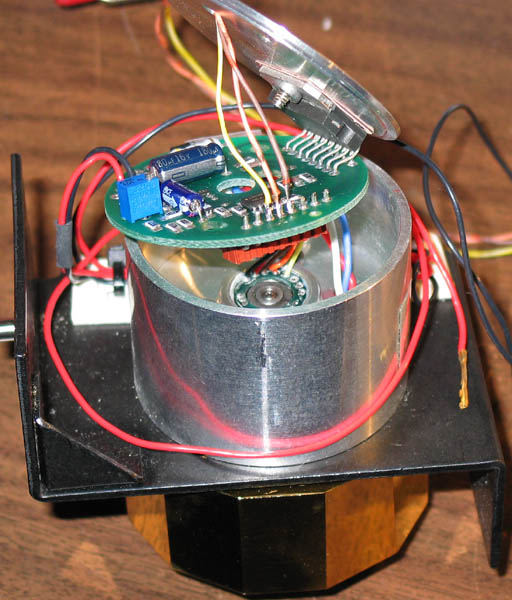
If I want to build a scanning laser display from this device, I need a timing signal. I opened the case in the hopes of finding some way to extract a signal (see the photo below). Fortunately, it was quite easy to extract timing signals. The IC which is connected to the bottom disk is a 3-phase motor driver. Its output is the thick red, white, and blue wires. The IC depends on timing signals for feedback, from hall-effect sensors. These are the thin yellow, orange, and brown wires coming from the center of the motor. I attached wires to them and routed them through the hole for adjusting the potentiometer.
Next I need a laser. I picked up some laser modules from aixiz on ebay. The first ones were 5mw, 650 nm modules. While these worked fine, the resulting image was a bit dim. I wanted to get a brighter image, but I didn't want to use a higher power laser because of the danger of burning out my retinas. Instead, I picked up some 5mw, 635 nm lasers, which are much brighter to the human eye (green lasers are even brighter, but much more expensive). Both the 635 and the 650 nm laser modules required some surgery before I could use them in the scanning laser display. Laser modules (as opposed to laser diodes) come with current regulating circuits to protect the laser from voltage spikes. A solid state laser is basically an LED with two polished ends. The ends of the LED act as the mirrors, creating the lasing cavity. The energy density is very high, and over-power conditions will damage the "mirrors" resulting in a significant decrease in efficiency. Part of the regulating circuit is one or more capacitors to filter transients. However, I will need to switch the laser on and off rapidly but the capacitors will tend to turn the laser on and off slowly. So, I need to remove the capacitors form the laser module. In the picture below, I show one 635 nm laser module with its protective endcap, and another with the endcap, and also its capacitors, removed (one capacitor between the power and ground).

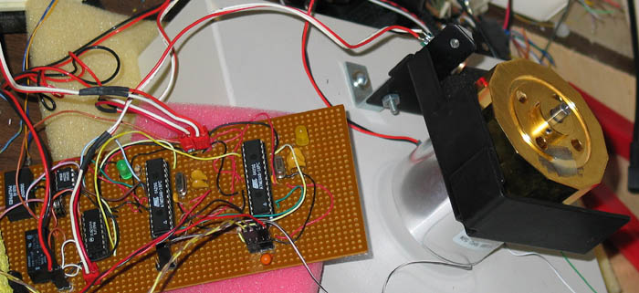
The image below shows the complete system, but not yet assembled into its box (a repurposed external CD-rom drive). Since I expect to put the completed system in an inaccessible place, I built an IR remote control interpreter (the ATMEGA8 on the right). I picked up a bunch of IR remote controls and IR receivers for a low price, and developed a program which prints out an ascii code on its UART in response to a button click (I used a helper processor because the timing requirements for the scanning display are kind of tight). The ATMEGA8 to the left reads the timing signals and drives the laser. I have also attached a ds1302 real time clock, a ds32khz crystal, and a relay for turning the spinning mirror motor on and off (controlled by the helper microcontroller). You can also see the laser mounter to the motor casing.
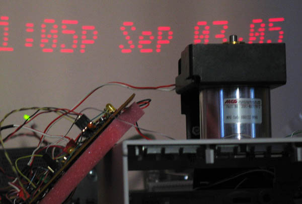
Below is a picture of the display in action. The motor scans at about 30 rps, and has 12 sides. So each line is scanned in less than 3 ms, and I use most of the scan line for the display. Therefore, I use only 8 of the 12 scan lines for displaying text. During the 1st scan line, I perform some precomputations to make scan position computations faster, and during the last 3 scan lines I read the UART and interpret commands, query the DS1302, and compose the text for the next scan. One issue I faced was finding a good interrupt point. There are three signal lines, each of which recieves two pulses per rotation. I chose the line which produces the best grouped set of scan lines immediately after the interrupt (the interrupt will also occur in the middle of the 1st scan line, which requires some additional handling).