Emotilock
I purchased a set of small projection displays (antique display technology); one collection of three displays in reasonable good shape (below), and another which consisted of a small and a medium sized one in poor shape. Even the ones in good shape were missing pieces, e.g. no front screen and one missing bulb holder.
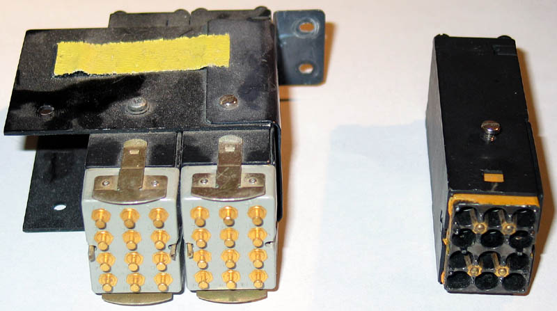
I wanted to do something creative with the displays. In honor of the 25th anniversary of the emoticon, I decided to make one of the displays show smiley faces (OK, it was actually my wife’s idea). I’d need to fit a 12-hour display into one of the other displays (having only four total), and to make the fonts consistent I’d need to replace the projection films for all of the displays. Therefore, I’d need to crack all of these rare, expensive displays open! Its time for a projection display autopsy. To start, we can see the front of the display below, including the holders for the now-missing projection screens.
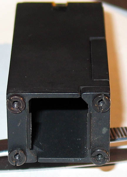
Here is a closeup of the back of a display which still has a bulb holder.
The bulb holder is held in place by the gold-colored clips. By removing it, we can see that that the bulb holder consists of gold-coated springs pressing against small bulbs.
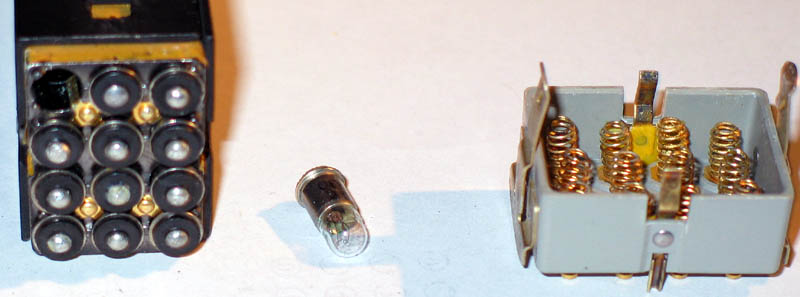
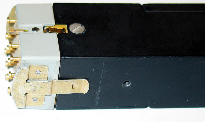
The shell of the display consists of two pieces, with screws at the front and on the internal bulb holder. Below is the display cracked open and showing the lens assembly.
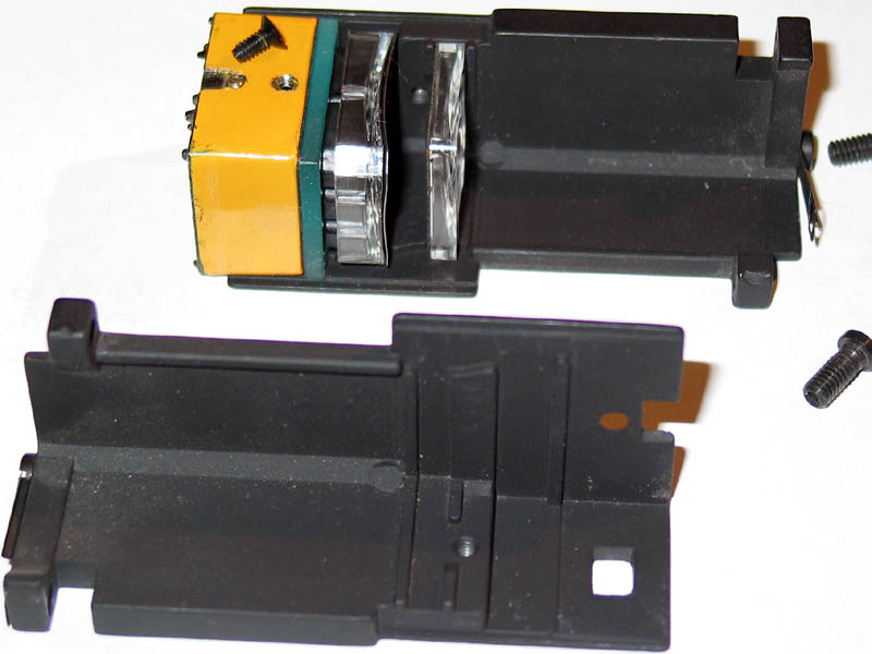
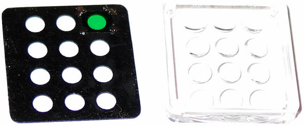
Light from the bulbs in the bulb holder project through a first set of convex lenses mounted on a concave platform, to a second set of concave lenses again mounted on a concave platform. Immediately after the first lens array is the lettering film held in place by a metal grid, and immediately before the second lens array is a plastic aperture, one of which has a green gel attached.
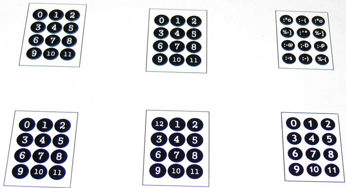
By replacing the lettering film, I can make the display project my own characters. However, the positioning of the characters on the film has to be pretty precise. Below is a set of samples I printed on paper to see how the fonts look and to check for fit.
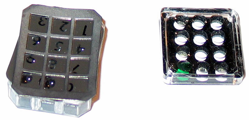
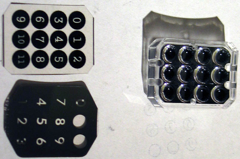
Below is a closeup of the first lens array with the old character film and the new character film.
Here is a closeup of the second set of lenses.
I decided to drive the projection display using LEDs (I had to since I had only two bulb holder backs for four displays). To make things more interesting, I use three-color (RGB) LEDs. I found that the cloudy LEDs give a better image, so I build an array of them, as shown below.
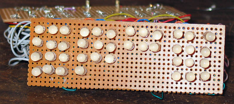
The wiring was pretty nasty, the less shown the better. To finish up, I put the four displays in a rack, inserted the LED array in the bulb holders and powered it up. All I need is a screen. My first try at a screen was a ¼ inch thick piece of translucent plastic. Unfortuantely, it was blurry and not so bright.
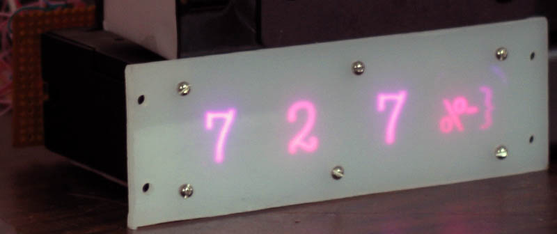
The problem is that the translucent plastic diffuses the light from the projection display (making it blurry) and also diffuses light entering from the front, sides, back, etc., swamping out the display light. I decided that what I needed was an extremely thin layer for diffusing the light. So, I took ¼ inch sheet of clear plastic, and scratched one side with 300-grit sandpaper. The result was a much sharper and brighter screen as shown below.
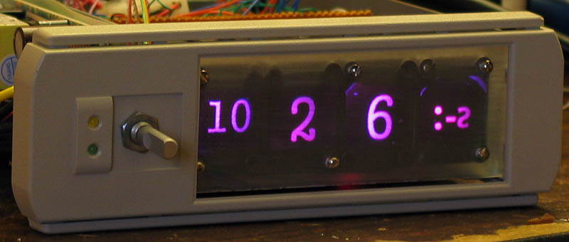
The only problem is that the display is highly directional – very bright straight on, dim from the sides. But at least its visible in a sunlight room, so I stuck with it. I’ve read that there is a huge technology behind LCD and projection screens – now I start to understand.
Some notes on the LED driving and the software. I use a TI TLC5940 to drive the RGB LEDs, as it provides 12-bit dimming as well as constant current LED driving in a hobbyist-friendly PDIP package. There is one weird thing about the TLC5940: you must a) provide a clock signal (to drive the PWM), and b) you must provide a reset signal once every 4096 clock signals (via the BLANK input line). Requiring a clock input maybe saves the need for an RC circuit in the chip, but requiring the reset signal seems punishing without providing any extra flexibility and saving only a couple of gates. Fortunately the Atmel AVR line has a) a full-swing oscillator mode capable of providing a clock source, and b) can implement a 2-cycle interrupt handling routine for producing the reset signal ever 4096 cycles.
To take advantage of the RGB LEDs I implemented a color wash algorithm. I’d done a color wash algorithm previously to illuminate a flip-clock, but wasn’t completely happy with the results. I wanted to keep the illumination at constant brightness, e.g. maintain the invariant R+G+B=N. This is possible by making a random walk in a triangle with sides R=0, G=0, and R+G=N. Given a position in the RG triangle, set B=N-R-G. However, I found that the colors were best nearest the side of the triangle, and worst nearest the center. That is, the closer you are to white light, the worse it looks (at least using a single RGB LED). So I implemented a color wash which walks along the sides of the RG triangle completing a circuit in about 3.5 hours.
The code for the clock is here.