Seven Segment Neon Clock
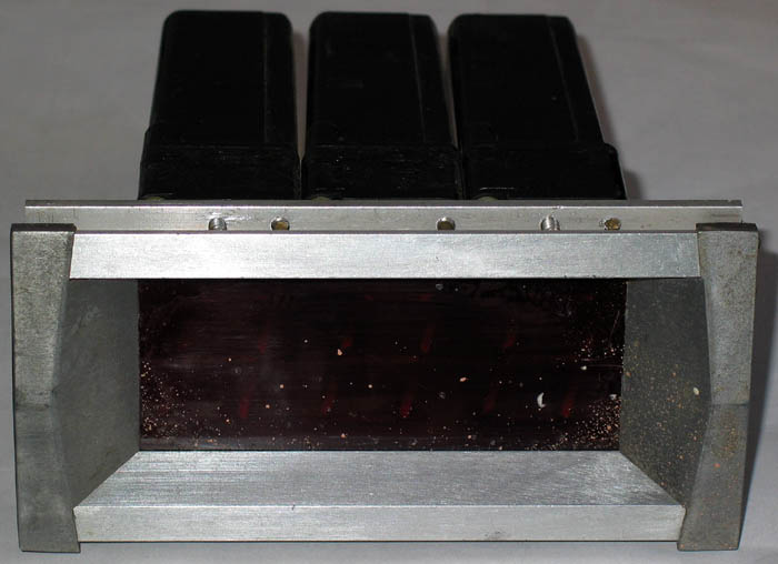
I picked up some unusual displays at a low price from a surplus store. At first sight, they didn't look promising:
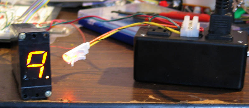
I removed the displays from the dingy bezel, and discovered that they are 7-segment displays lit by neon bulbs, with the digit being 1.25 inches tall. I sacrificed one of the displays to determine its inner workings, and managed to get them to light up. The displays use two power supplies, 120V AC and 12V DC. Each display has a 4-bit binary input and a strobe input. These inputs seems to be diode protected - enabled by pulling them to ground, but I use a pull-up to 12V just to be safe. Some of the displays (the 321-e2-p-12) also have a decimal point. Although the display seems to take a significant fraction of a second to change values, the length of the strobe can be short - I wound up using a 5ms strobe. To safely test the displays, I built a box for supplying line power, as shown below:
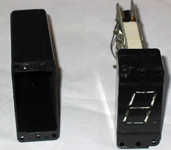
To determine how the display works, I cracked one of them open. Here is one with the case opened:
Below you can see how the neon bulbs fit into the display box:
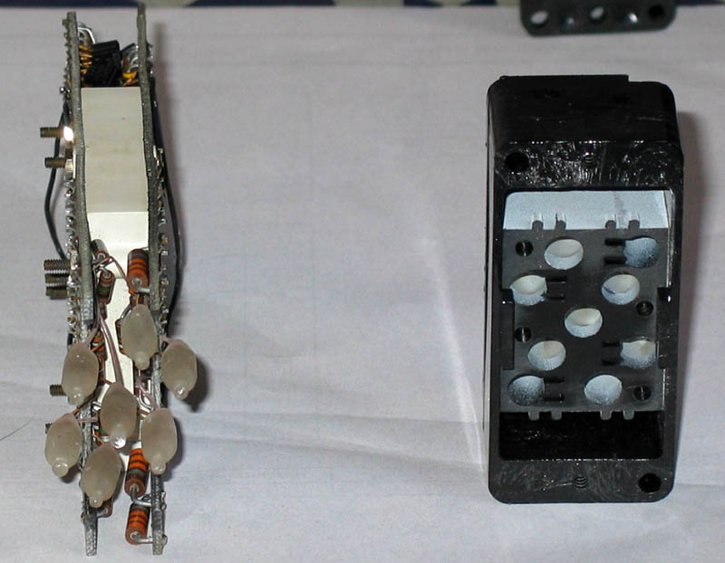
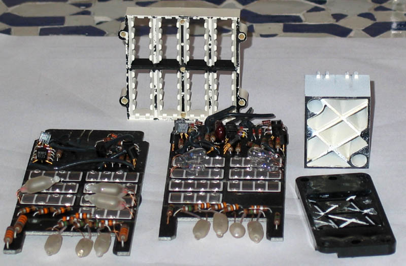
I separated the two PCBs to show all of the parts below (to do so, I had to cut a tangle of wires connecting the two boards). The white rectangles with the four dark brown rectangles are photo-resistors (each brown rectangle is a separate resistor). Each of the photo-resistor arrays can be activated by the light from a bulb - in 4 cases, a 12V incadescent bulb, and in 3 cases a neon bulb. The white plastic casing with the eight cutouts separates the two PCBs and provides separation between the lighting chambers. I've also opened up the casing for the display, shown on the right.
I'm not certain of exactly how this display is supposed to work, but the photo-resistors seem to be opto-couplers which allow the 12-volt signal to control the 120 VAC neon bulbs (the switching isn't purely optical, as evidenced by the transistors). I wasn't impressed by the build quality of these displays, given all of the hand-wiring that they use (and which must have made them quite expensive). And in fact, about half of the displays wound up being duds, which I could sometimes trace to a wiring problem. If you use these displays, be cretain to test them before installation. However, each display is quite cheap and the duds yield a nice quantity of interesting parts.
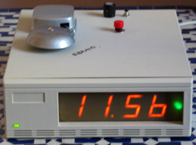
I used four of the displays to build an alarm clock, shown below. The case is from a discarded 8mm tape drive - quite heavy and durable, and has some enigmatic writing on the top. The displays wound up fitting into the case almost perfectly. Since this is supposed to be an alarm clock, I put a bell on top. I'd planned to use a nice small black bell, but it requires 24V and the power supply in the case provides only 5V and 12V. Instead, I purchased a ringer from a hardware store, bypassed the mechanical interruptor, and mounted it on the top of the case. A 10ms pulse of 12V produces a nice ring. The red button is the snooze, the alarm switch is in the back (the alarm-on indicator is the orange dot on the upper right). I covered the front of the display with a pice of tough translucent brown paper, which hides the ugly workings inside. The displays project their light a couple of millimeters onto the paper, which softens their lines a bit.
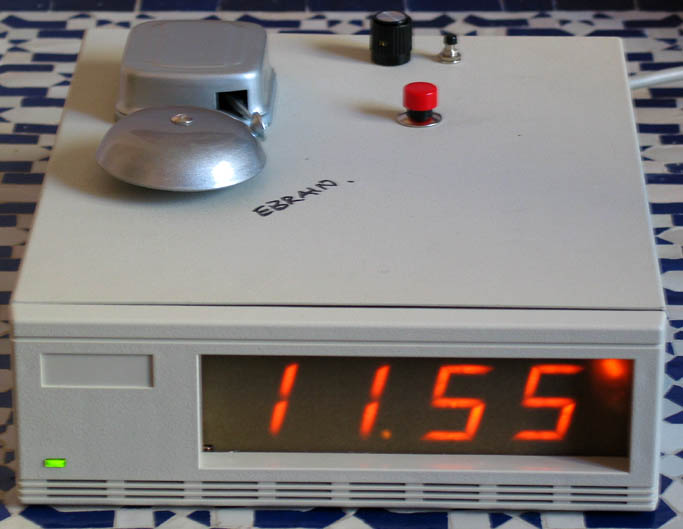
Here is another photo, showing the change-hours indicator. I used a green neon bulb for to indicate changing hours, and a blue neon bulb to indicate changing minutes.