Coax cable length dependence
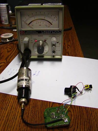
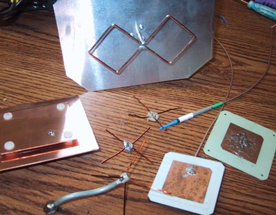
Picture of my testing setup. General microwave powerhead/tester connected to XCam-2 output through RG-174U cable. The powerhead has N-type RF connector. I have fitted it with N to SMA adapter. The tested cable is soldered to SMA connector at one end and to XCam2 PCB at the other. Numbers may have 20-30% absolute error because the device is not calibrated but relative results are reproduced within 5% margin. Some of the test results: Best coax arrangement is in the plane of PCB, as shown in the picture. This arrangement gives 4.5 mW output compared to 3.8 mW when coax cable attached to PCB at 90 degree angle. That is roughly 20% more power.
Here is a power output measured from RG-174U cable of different length, I was trimming
the cable from 9.5' long to 5.0' in 0.5' increments.
Length (inch): 5.0 | 5.5 | 6.0 | 6.5 | 7.0 | 7.5 | 8.0 | 8.5 | 9.0 | 9.5
Power (mW): 5.5 | 4.4 | 5.2 | 5.5 | 4.5 | 4.9 | 5.2 | 3.7 | 4.5 | 5.5
It looks like there is slight dependence on cable length caused by mismatch in probe
impedance with characteristic 1/4 wavelength period.
To compare different cables/cable length I've made 2 more measurements. I did not
trimmed the cable to achieve maximum power output for these measurements:
Power out from 15 inches long RG-178U (thin coax cable used in XCam2) cable is 4.8 mW .
Power out from 5.5 inches long RG-58U cable (thick 5mm diameter) is 4.5 mW.
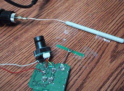
Coax/antenna testing
In these tests I have connected XCam2 to a dipole antenna and positioned the antenna some distance away from dipole receiving antenna. Receiving antenna is connected to a General Microwave power meter.
Test #1. RG-174U cable. Transmitting antenna is taped directly to a receiving antenna. I am trimming coax length from 4" to 1.5" in 0.5" increments.
Coax length (Inch) 1.5 2.0 2.5 3.0 3.5 4
Power measured (mW) 0.6 1.2 4.0 0.8 1.0 4.0
This is a huge dependence! Power changing by a factor of 5 in just 0.5" change of coax length.
Test #2. RG-178U coax cable. Transmitting antenna is 2 inches away from receiving antenna.
Coax length(Inch) 1.5 2.0 2.25 2.5 2.75 3.0 3.5 4.0 4.5
Power Measured (uW) 7 13 27 18 10 7 7 25 7
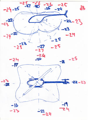
Antenna radiation diagram
Distribution of radiation power depending on horizontal and vertical angle from the transmitting antenna. Blue numbers for dipole mounted antenna right under the battery, red numbers for dipole antenna mounted on the tail of helicopter. The numbers (dBm) of power received by dipole antenna 6 ft away from transmitting antenna
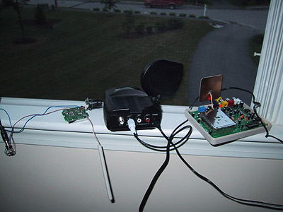
LOS range
XCam and Racewood Technology receivers positioned for LOS testing of XCam2 transmitter
Selecting receiving antenna:
It was not easy to find best antenna for the receiver. The goal is to get a uniform
coverage of the airspace without additional person pointing antenna at the helicopter. I
felt that a turnstile antenna quarter wavelength above ground plane is a good choice but
so far my efforts to built it have not realized. On the other hand a good directional
antenna with 15 dBi was fairly easy to build according to http://www.wlan2.dabsol.co.uk/simple_double_quad.gif
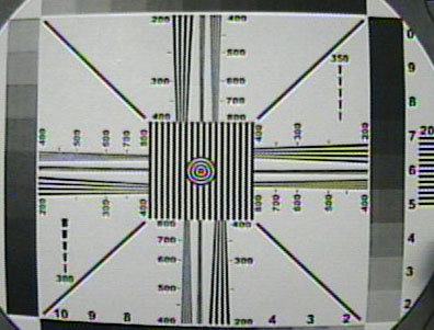
CCD Resolution testing of Panasonic's GP-CX171 CCD
Using GP-CX171 connected to SONY TRV103 Digital8 recorder video input I recorded the standard TV test pattern and then downloaded the image on PC through firewire port. The observed resolution was around 420 - below declared 480 but still about 50 lines better than resolution achieved using SONY TRV103's CCD sensor.