 |
 |
 |
 |
 |
 |
Introduction:
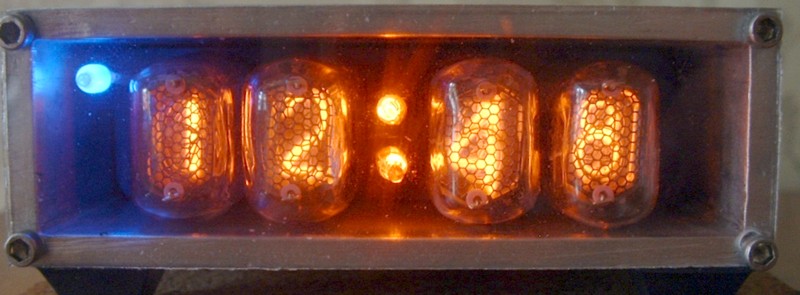
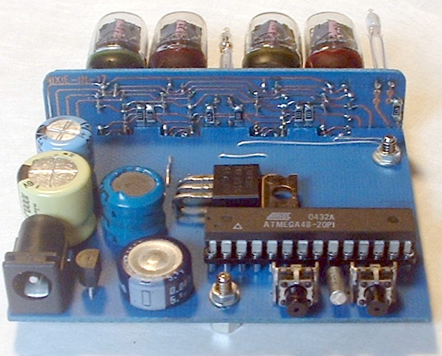
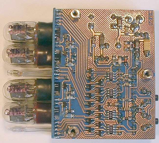
This is the hardware and source code for an Atmel ATmega48 based four digit Nixie Tube Clock.
Description:
This was my second Nixie clock project. I wanted something a little smaller / cheaper / simpler then my rather large B-7971 clock. I will post the design for that one of these days. I was trying to simplify everything. And basically wound up with a one chip solution, ... the micro itself does just about everything.
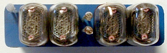
The Nixie tubes are relatively cheap and available (Ebay) Russian IN-17s.
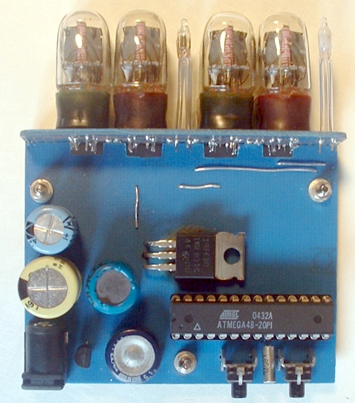
Discrete transistors drive the tubes in a 1x4 mux arrangement. Needs 15 I/O lines from the processor.
No external RTC chip. Saw no need for 10 years backup with a lithium battery. Really just wanted a few hours to handle the typical short term power outages I get so I don't have to reset the time too often. The mega48 has some very low power operations and support for an asynchronous xtal clock that's perfect for RTC functions. This alone makes the newer Atmels more attractive for clock designs. A relatively small 'supercap' provides back up power during mains outages (8-12 hours).
The high voltage is generated with an fet and inductor connected to one of the PWM outputs on the chip. The voltage is measured via one of the A/D channels, and the PWM value is adjusted to provide regulation. The voltage van be adjusted via push buttons during set up and the value is stored in non-volatile memory (no voltage adjustment pot)
No alarm / speaker / temperature / Westminster chimes on this design, I wanted simple.
Two push buttons provide a user interface to set time and options.
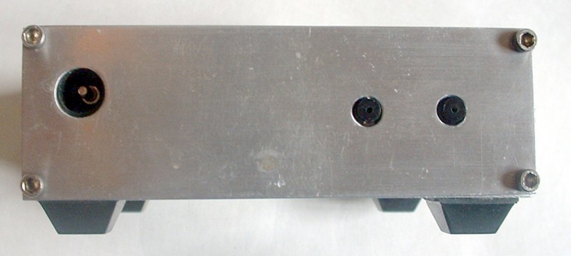
A simple extruded aluminum case finishes the design.
Pictures
Click to enlarge
|
|
|
|
|
|
Existing Issues:
I'm pretty happy with the design, but there are two areas that I'd like to improve:
The time base is completely tied to the 32,768 xtal, and is very thermally sensitive. I did not line lock this design and the accuracy shows it. At some point I'll add a time correction factor to the setup.
The regulation on the HV power supply is not the best. There is a lot more interaction between the MUX rate, the ADC sample rate, and the PWM frequency / duty cycle then I would have normally imagined. The feedback loop code could use some more adjusting (or an entire re-design) by someone who knows what they are doing.
Legal Stuff:
This source code and hardware design is made available for educational and non-commercial use.
Commercial use is forbidden without license from author.
Code may be modified as long as it is released publicly and credit is given to the original
author(s).
Copyright © 2005 Henry Carl Ott N2RVQ, all rights reserved.
Any questions, comments or offers of cash? mailto:carlott@si.rr.com
, H. Carl Ott's Home Page
Disclaimer:
This design is provided as is with no guaranties.
Do not use this design where human life is at risk or where
property damage may result.
Project Downloads:
| *NEW* Rev 1.1 Code and schematic. | ||
|
|
Older Downloads: |
|
| Schematic page 1: CPU | ||
| Schematic page 2: Display | ||
| Source code for Atmega48 | ||
Construction Notes:
I designed two seperate PCBs for the clock. One for the IN-17 display, other one for the Atmel and everything else. It's a mixed TH / SMD single sided design with just a few jumpers. I used toner transfer to make the boards and I don't have any extras. If people are interested, I can provide artwork. The traces on the display boards are a little on the fine side and it was a little tricky to fabricate. I used all smd transistors for the HV drivers and some pretty small resistor networks to get everything to fit the way I wanted. A lot of the parts were surplus items I had laying around the shop, so I really don't have a detailed BOM with digikey numbers for everything. Nothing is too critical and you can make substitutions.
Enclosure:
I used a 1x3 inch piece of extruded aluminum. Commonly available. Cut to length. I finished the ends and drilled and tapped the corners for some 2-56 socket head screws. A piece of punched sheet aluminum for the rear panel and a small piece of clear lexan finishes up the front. Not too shabby. I have a lot more trouble with the mechanics of building nice enclosures for these clock, then with the design of the electronics.
And if you have any questions or comments please email
me: carlott@rcn.com
Henry Carl Ott N2RVQ
![]() Back to my home page
Back to my home page
Page hit counter:
Last revised October-2005