I decided to make an interesting clock frm one of the edge-lit displays that I had picked up (details are here). I found that 3mm LEDs fit the holes in the edge-lit display pretty well, so I could replace the lamps with LEDs. Instead of using all of one color, I could use a variety of colors. It took a bit of searching (5mm LEDs are more common than 3mm), but I found the following:
| deep red | 660nm |
| red | 625 |
| orange | 605 |
| yellow | 588 |
| yellow-green | 565 |
| green | 525 |
| aqua | 505 |
| blue | 470 |
| violet | 420 |
| white | - |
| pink | - |
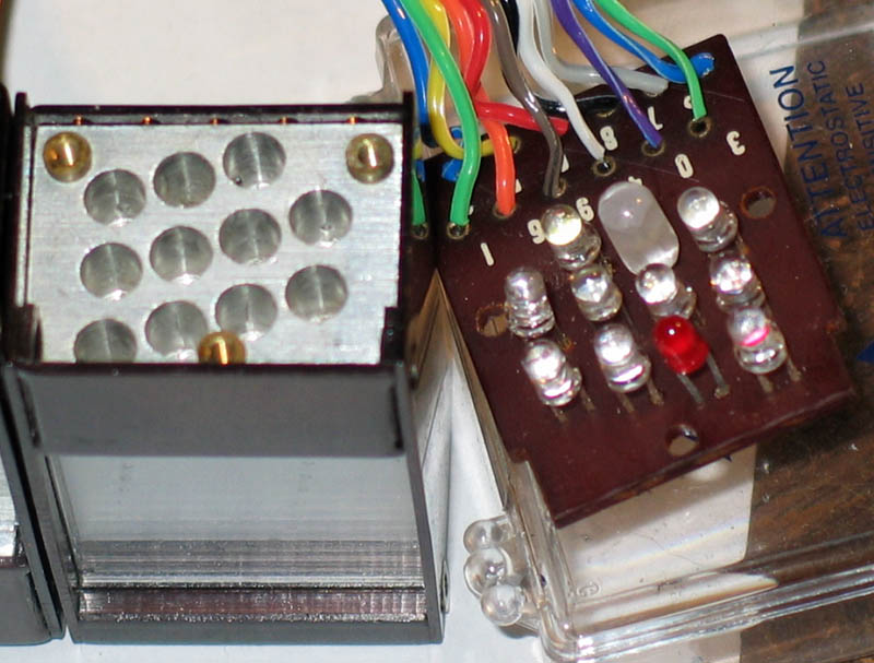
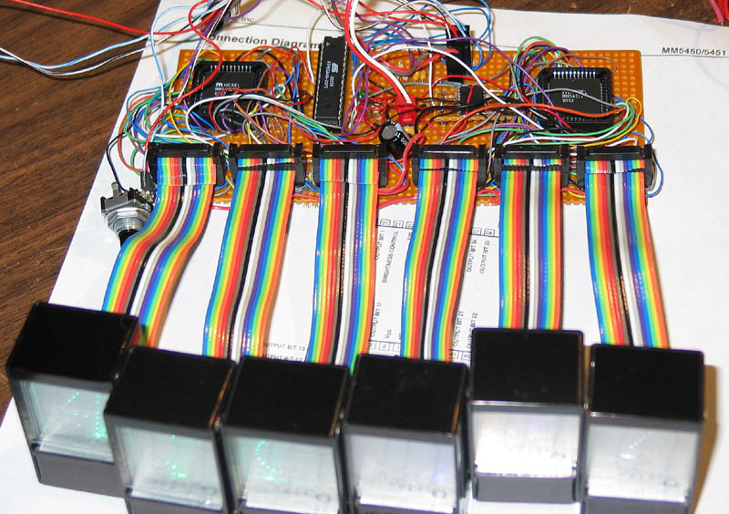
I decided to arrange them as a spectrum, assigning deep red to 0 through violet for 8, then completing the spectrum by assigning white for 9. pink is outside the spectrum (being a mixture of red and blue) so I use it for the dot. Below is a picture of the LEDs soldered to the board which used to hold the incadescant lamps. You'll notice that the violet LED is actually a 5mm one, which I filed down to fit in its socket.
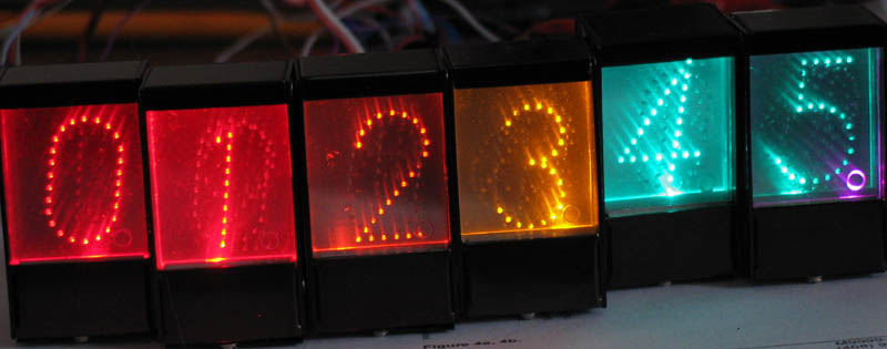
Below are the digits 0 through 5
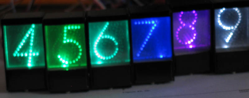
and the digits 4-9. The main glitch is that the 4 is more of an aqua than a yellow-green. I selected this LED from digikey using their parametric search, and it seems that they entered the wavelength wrong, since on the catalog page its listed as being aqua.
Below is the board. I used two Micrel MM5450 LED drivers (used to be National Semiconductor MM5450). These are nice drivers, providing 35 constant current sinks. The only problem is that the documentation is lousy -- the Micrel data sheet doesn't even explicitly say that they are sink drivers. The data sheet is also extremely vague about how to choose the reference resistor (for the current limiting circuit). I experimented a bit, and found that a 3.9K resistor creates an 11ma driver. I thought I had asked digikey for pdip drivers, but they sent me plcc. Through-hole plcc sockets are inexpensive, but they have double rows of pins, which makes the wiring difficult. I took double care in doing the wiring, which paid off because surprisingly I made no mistakes.
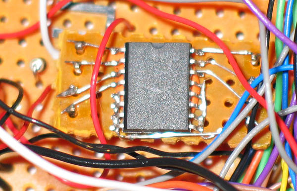
I used the new DS3231 integrated calibrated crystal/RTC. Unfortunately its only available in a very wide-body SOIC, so I couldn't even use my adaptor boards. Fortunately, SOIC is large enough that its relatively easy to solder wire-wrap wire to the pins. I attached wires to the bottoms of the pins, and created the socket shown below. I hold the DS3231 in place using tack putty, which is the orange stuff.
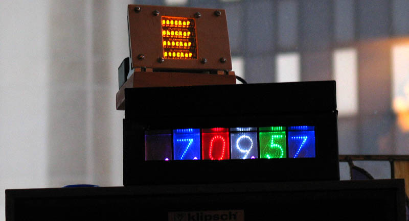
For a case, I used a steel 3x5 index card box that my wife was discarding. The finish was kind of scuffed, so I applied a coat of liquitex black glossy enamal paint (cured by baking it at 375 for 45 minutes). The display on top of the clock is another 8-letter word.