Remembering the Rutland - Forums
The opinions expressed are those of the writer and not necessarily of the editor.
Athearn Light Mike Forum
Rutland 2-8-2 #34 is coaled and watered and ready to take a
freight train of Boston-bound tonnage over Mount Holly.
--Photo taken by Donald T. Hayward at Rutland, VT, August 6, 1947--
--Collection of James R. Dufour --
Introduction:
The Rutland Railroad acquired six 2-8-2 Mikado-type locomotives in 1918. These engines were built by Alco's Schenectady Works to the United States Railroad Administration (U.S.R.A.) specifications for a light 2-8-2. They were classed H-6-a on the Rutland and formed the backbone of the Rutland freight-hauling fleet until the arrival of the diesels in the early 1950s.
Until recently the only way to accurately model this class of Rutland engine in HO scale was to purchase an expensive brass import such as was offered in the past by Key or Pacific Fast Mail or a pseudo-brass import, i.e. the Oriental Powerhouse series.
After a lot of anticipation Athearn released their HO scale USRA Light Mikado in 1999 (the undecorated road pilot version is Athearn catalog # G9000). This is the one that Rutland modelers had been waiting for. It joined the footboard pilot version (Athearn catalog # G9001-undecorated) which had been released earlier. These models were assembled by Korean builder Samhongsa, whose reputation for beautiful detail and smooth-running mechanisms in the brass field is legendary.
In February 2001 Athearn had a booth at the Amherst Railway Society's Springfield (MA) show and heard first hand from Rutland modelers (in particular Bill Badger) that they should consider producing a run of their 2-8-2 custom decorated for the Rutland. It didn't hurt that Lou Sassi was displaying Don Janes' rendition of Rutland Mike #37 on one of his modules nearby.
Assembled below in chronological order are some of the comments that I received after the initial release of the model followed by the correspondence leading up to the release of the custom decorated Rutland version. When that model is released I would anticipate a hearing from you with your reactions.
General Topics:
General comments on the Athearn USRA Light 2-8-2
Correspondence regarding Athearn's Rutland version of the USRA Light 2-8-2
Peter Berg modeled Mike #34 by starting with a PFM brass import.
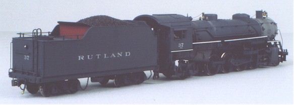
Don Janes modeled Mike #37 by converting the Athearn model.
Kevin Kelly's method for the installation of an operating front coupler
|
Another view of Don Janes' customized Athearn Mike detailed for Rutland #37 |
Chuck Hladik's Initial Impressions
(10/16/99)
Haven't yet gone point by point on the Athearn 2-8-2 vs. Rutland, but have run one here at the shop (Trains Unlimited, 6010 Fort Ave. Lynchburg, Va. 24502) and the darn thing starts off with less juice than a Proto 2000 GP 30 and CRAWLS. There is NO comparison with the Bachmann 4-8-2, the Athearn just outperforms it tremendously.
All of [these impressions] are while viewing Nimke's Volume I, therefore I can't answer rear view shots. The Athearn loco I used for this adventure is undecorated w/foot boards. Can't find the box to give you the Athearn part number. Hope this is sorta what you asked for and my first attempt. I'll let you guys argue over white vs. silver lettering.
Overall impressions:
Nice.
Paint is even.
Length about right, tender about 3 feet too long overall.
Runs real nice, starts with less juice than a Proto 2000 diesel.
Drivers are correct 63".
Sanders are molded on and not quite right, but....
Tender:
Top of coal doors need cut down.
Trucks look good.
Truck centers correct.
Need deck handrails.
Ladder on wrong side, on undec it's not mounted but there are holes for it.
Unknown about water hatch.
Locomotive:
Top front of smokebox bell mount.
Two too many cooling coils conceal air tank on fireman's side.
A lot of plumbing missing from steam turret on fireman's side.
Check valve needs to "sweep up" below steam dome on fireman's side.
Shroud needs to be removed from behind pop valves.
Needs marker light conduit over/around top of smoke box.
Needs step under marker light on engineer's side, unknown on fireman's.
Handrails and additional plumbing are very discrectionary.
Recommend detail parts:
Marker lights - Cal Scale #190-280
Pilot - PSC #585-3430 (Rutland)
Pilot - Cal Scale #190-318 (looks close)
-Chuck Hladik
More Modification & Additions
by Anon.
(10/17/99)
The handrails at the front end will need to be reconfigured.
The headlight will need to be replaced.
Injectors, depending on era.
Barco low water alarm (Precision Scale)
Tender sides, depending on engine number and era.
Don Spiro Weighs in on the Road Pilot Version
(10/31/99)
I think the model is excellent. To my eye this locomotive captures the signature look of a USRA light. Yes, unlike the Bachmann locomotives, some piping such as the sand lines is cast on. But hey......this is "MODEL" Railroading isn't it??! That which is cast on is not offensive should plastic surgery [there's a pun there somewhere -jrd] be a strong suit.
Out of the box and onto the track with no lubing, it ran like a Porsche 911...throttle response is incredible and has that wondeful "crawl" we have come to take for granted from Kato/Atlas diesels. The valve gear is fine though a bit on the garish side in chrome. But then again, when was the last time you didn't see similar shiny valve gear on a Samhongsa or any other manufacturers brass steam locomotive? Any good blackening techniques that might be shared? [see below -jrd]
In some areas such as the cab the detail is better than on the Bachmann locomotives. The tender is slightly different in size, who is correct? I leave that to those more fluent in "Steam Speak."
OK, we expect some criticisms so here are mine and I don't find them [to be] reason not to purchase this exquisite locomotive:
1. The cast on pilot coupler is a throwback to the Lionel 2035 steamer....I expected at least a pilot coupler from Samhongsa.
2. No electrical pick-up on the tender. This causes the locomotive to hesitate slightly at times at slow speed through Atlas code 83 #6's. The problem has not happened though through Walthers/Shinohara code 83 or 70 turnouts on my layout. I plan on adding insulated metal wheels and MDC pickups on the tender. Which brings up #3...
3. The wire bundle with the DCC hook up looks like it's off a Mike's Train House 3-rail locomotive. I am impressed with how well it hides itself merely stuffed into a slot in the tender when no decoder is in the tender. I imagine this locomotive is very user-friendly for the digital modelers but I am a toggle thrower. Perhaps someone could explain which wires to leave out of the harness when removing it when one wishes merely to add tender pick-ups? The instructions don't really get into the electrical aspects of the locomotive. Athearn is leaving it up to the individual to know how to do that, I am electrially challenged at times so I simply say "HELP!"
And for those knowledgeable steam modelers, a quick run-through of appliances, details and where exactly they should go would be helpful to those of us who put off learning about such things and built first generation RS's, Cab Units and Geeps - never once imagining that the year would come when we suddenly had a trio of incredible steam locomotives both from an aesthetic and operating point of view. Is this the best time to be in this hobby or what!
A little later Don adds...
Thought you'd like yet another update...Now bear in mind I am not a Rutland modeler per say. I freelance based on the Susquehanna and the Rutland. However my steam is detailed and numbered according to Rutland practice. This morning I got out the paintbrush and took care of some of the offending cosmetics (or should I say lack of cosmetics?) and the results were stunning.
That black acetal/engineering plastic used on components hides much of the fine detail, particularly the trailing truck. I whitelined the running boards, painted the cab roof and tender deck oxide red and the tender trucks and wheels, trailing truck and wheels, and pilot wheels grimy black. A 100% improvement over "as-delivered."
I did notice a bend in the eccentric rod on the fireman's side. Once [this was] straightened the locomotive ran even smoother than out of the box! I also changed out the tender wheels but have no MDC pick-ups on hand. (Finding out the mysteries of the DCC cable and what wires are what would be extremely helpful in adding tender pickups.)
Like a house, sometimes a coat of paint does wonders. In this case, even
without a single, additional detail the locomotive is emerging out of it's black
enginnering plastic shell.
Regards,
-Don Spiro
Blackening
Those Garish Rods
(10/31099)
After reading Don Spiro's comments and in particular his inquiry about blackening the side rods on his steam locomotive, I telephoned good friend and modeler extraordinaire Tom Speidel about this problem. A while back Tom had shown me a brass steam locomotive that he painted for someone. What really caught my eye was Tom's treatment of the side rods, which looked extremely realistic. According to Tom he used a blackening agent that is sold in gun shops and gunsmith supply houses called brass black. It is recommended for use on brass, bronze and copper and is sold under the Birchwood-Casey name and manufactured by Birchwood Laboratories of Eden Prairie, MN 55344. They also make a similar treatment for aluminum called aluminum black.
BUT BE CAREFUL! When using any blackening agent be aware that the agent is capable of dissolving the thin insulation between the driver tire and the driver on the insulated side of the locomotive. Use caution around those drivers! It is also a good idea to try it first on a hidden part of the locomotive in case the results are not what you want.
-Jim Dufour
Cautions, Gripes and Accolades from Jim Otto
(11/03/99)
The engine itself. Weeellll, I like it . . . but it has it's drawbacks.
I don't like the smokestack assembled from a separate piece, the seam is very noticeable. The bell doesn't have to be moved for Rutland, if you're modelling an earlier time. Photos in Nimke Vol.1 shows several mikado views with the bell the same as the Athearn model. I don't like the fact that their are no pickups on the tender trucks either. I don't like the fake coupler on the front of the pilot.
Those are my gripes. Here's my accolades.
I think it runs fantastic. I only have a test track in operation right now, but back and forth a few times right out of the box it ran very smoothly, especially at slower speeds. I ran it right next to a Bachmann 4-8-2. At slower speeds the Athearn just kept running where the 4-8-2 stopped. The Bachmann engine also seemed to run slightly faster at higher voltages. No concern here, except for the missing coupler on the front, can't double head. I'll buy one . . . I mean, I'll keep the one I bought.
-Jim Otto
Oh Oh!-Part 1
To: Athearn (via email)
cc: Remembering the Rutland
Yesterday, November 2nd, UPS delivered my Athearn Genesis Light Mikado 2-8-2 #9000.
I placed it on my layout for a trial run. Everything went well EXCEPT that it
derailed on the frogs of several of my turnouts. I might add that this has not
occured with my dozen or so other brass, diecast and plastic steam locomotives in the nine
years that my layout has been in operation.
Close inspection developed that the right hand (engineer's side) #3 driver's tread does
not touch the railhead. In other words, seven drivers are firmly on the rail, while
the RH #3 remains in a "hung up"
position. Also, according to my NMRA track gauge, the #2 pair of drivers are
slightly narrow in gauge.
What steps are you willing to take to assure that I am satisfied with the operational
qualities of this product??
-Dwight Smith
Oh Oh! Part 2
(11/08/99)
Jim:
Under your new Athearn Mikado web page, I see my "Oh Oh!" item. Just to let you
know that John Engstrom of Athearn promptly E-mailed me with instructions
to return the loco to him for repairs and prompt return. So I fired it off to Compton, CA
and hopefully will get it back soon. After hearing from Athearn I also heard from Train
Works, with their willingness to exchange for another unit. So whatever
dissatisfaction I may have had was quickly dispelled by the prompt and courteous replies
from the manufacturer and the dealer.
In going through photos of the Rutland mikes in my collection and in Nimke's
Rutland books I note that the most obvious difference between the model and the
real thing is the placement of the bell. All my pre-1940 photos show the bell on
the top front of the smokebox front, as done on the Athearn #9000 road pilot unlettered
version. My photos that start in 1941 and ending with their last gasps in the 1950's show
the bell atop the smokbox itself, just ahead of the stack. It is a bit harder to discern
actual dates in Nimke's books, as he is a firm believer in not dating his photos.
The best photo I have ever seen of a Rutland mikado, is the shot of No. 35 on page 17 of
Nimke's Rutland volume VII.
I was pleased with the Product Review on page 16 of December '99 Model Railroader,
especially with the instructions on how to disassemble the unit for kit-bashing.
-Dwight Smith
Oh Oh! Part 3
(12/03/99)
By referring to the instructions in the December Model Railroader's review of the Athearn Mike, I was able to completely disassemble my Mike in preparation for painting and detailing. A word of caution: be sure and remove the damper on the lower right side of the smokebox before trying to slide the boiler off the chassis.
In the Model Railroader article (page 17) they refer to firebox stays, when they mean smokebox stays.
While the tender was apart, I set the drawbar and truck nuts in GOO, so that it won't be necesaary to take the tender body off to retrieve the nuts every time I unscrew the drawbar or trucks.
I cobbled the tender's kit-supplied plastic coupler, and have placed it in the coupler slot of the front pilot. I then put a Kadee #5 on the tender. Now I can double head my Athearn Mike with my 1961 Akane light USRA Mike.
I am looking forward to someone coming up with some step by step instructions to install electrical pickup through the tender wheels. It will have to be a person that is less electrically challenged than I am. I find the wire snake between the cab and the tender to be most intimidating.
-Dwight Smith
Oh Oh! Part 3a - Roger Robar Lends a
Sympathetic Ear
(12/06/99)
Dwight:
I understand fully what you are going through with this model. It seems most everyone is having problems of some sort, be it wheel bearings, electrical, poor traction, tender not staying on the track and so forth.I highly recommend you go to TTX website (www.ttx-dcc.com) On his web home page he has news items listed, (one on the Bachmann 4-8-2 and the Athearn 2-8-2) and one he calls "Tony's Tips". Check these out, also he has a 'BBS' site (Bulletin Board Site) where modelers can ask and solve modeling problems. In the last few days there has been several responses to the Athearn 2-8-2 model. I have two responses in there too. These should help to over come your problems. As far as the cord between the locomotive and tender, CUT the heat shrink tubing off the wires, paint the wires black and they will hardy show.
I tend to think many modelers are comparing this plastic model with brass imports, a mistake! It is a quality PLASTIC model, nothing more and nothing less. With some work and fine tuning it can be a great model. The market is there for this type of model, look at what Bachmann has done and all they are going to do in the future. Athearn's first steam model isn't perfect but can be made better with some effort. One nice thing about styrene models is the fact one can 'bash' them into prototype models quit easy, look at all the detail parts we have at our disposal.
Sorry I rattled on so long, hope this info helps.
-Roger
Chris Martin on Springs, Wires and Tender
Boards
(11/08/99)
The solution that eventually worked for me was to replace the springs on the 2nd driver. Like most sprung steam engines, the springs used by the factory are WAY to stiff. The replacement springs I used were Kadee knuckle springs -- almost too weak, but they fit in the holes where the springs fit in the underframe, conduct electricity, are readily available, and, most important, allow more engine weight to bear on the lead driver. No more problem, and I'm getting a 2nd 2-8-2.
A thought on the tender. Athearn put higher than standard coal boards on their tender, which is excellent news for RUTLAND modelers, as the height looks to be about right for the RUT's tenders -- We just need to figure out how the curl the top edge over!
I also appended the wire list that will help folks like Don
Spiro who want to put some pick-ups under the tenders [read on below -jrd].
Yours truly,
-Chris Martin
Some people have had trouble keeping the front driver on the rails, presumably due to balance problems. Here is what Athearn had to say to Mr. Edward Oates, who emailed them about it:
It appears that in some locomotives the screw
holding the main frame, boiler and weight (the screw that goes up through the bottom of
the frame at the stack) is too tight, causing the frame to lift. They say that by backing
the screw out a little, it should realign the frame and alleviate the problem.
Additionally, however, we have found that the wiring harness that goes into the tender can
cause problems IF it is not straightened out and flexed a little. We have been able to
eliminate the problem with the harness in our testing here by straightening out the wires,
then flexing it to get the wires inside the shrink tubing loosens up. Here is some more
general information for you. The wiring harness of the Genesis Series USRA 2-8-2 Light
contains nine (9) wires. They are used as shown below:
Gray - Motor negative
Orange - Motor positive
Red - Right rail pickup (engineer side)
Black - Left rail pickup (fireman side)
White - Forward light
Yellow - Reverse light
Blue - Light common
Green - Function 1
Violet - Function 2
Note that although the yellow, green and violet wires are included in the shrink wrapped
harness, when used with DCC they would probably be separated from the wiring harness and
kept in the tender.
John Engstrom
Athearn, Inc.
19010 Laurel Park Road
Compton, CA 90220
That %#@* Stack, Tender Pickups & Handrail
Stanchions
(11/17/99)
The newness has worn off slightly and I can give you a few
more comments on the Mike. I'd heard on the net that people were less than thrilled with
the stack. Well I have to agree, the seam is a detractor but I haven't decided
whether to fill with putty and repaint or look for a replacement.
The lack of tender pickups is still the biggest annoyance, what Athearn was
thinking of or not thinking of I haven't a clue. I E Mailed MDC Roundhouse over
a week ago inquiring about buying tender pickups but still no reply.
Fianlly a request: I want to add the low railing
around the tender deck. I have seen a number of handrail stanchions for sale in the
parts section of the Walthers catalog but there are no photos. Does
anyone have a manufacturer and parts number for the proper stanchions I need to order??
-Don Spiro
Chris Martin Answers the Call Again!
(11/28/99)
Bowser - 2mm from base to handrail hole - #6000
PSC - 1.5mm from base to handrail hole - A-370
PSC - 2mm from base to handrail hole - A-371
PSC - 2.5mm from base to handrail hole - A-372
PSC - 3mm from base to handrail hole - A-373
PSC - 3.5mm from base to handrail hole - A-374
PSC - 4mm from base to handrail hole - A-375
The Bowser parts are $2 for pkg of 10, the PSC are $3.50 for a dozen.
2-2.5 mm is about right for the tender deck handrail. These are all turned brass pieces.
The problem that Dwight Smith found with his engine was probably caused by the hornblock sticking out too far. If anybody else has the problem it can be fixed by sticking a small screwdriver in behind the wheel and pushing the offending hornblock back so that it clicks in place.
I mounted front couplers by unsnapping the dummy coupler, drilling a #76 hole all the way thru the top and bottom of the coupler pocket and through the shank of one of the Kadee 20-series plastic couplers, and using a piece of .019" Detail Associates brass wire as a pivot. The #23 couplers come out about right. I haven't figured out how to make the couplers self-centering, but give me time!
Yours truly,
-Chris Martin
Works in Progress
(01/12/01)
Don Janes' Athearn conversion has led to a few more comments on the Athearn 2-8-2.
I've been working on two of them myself. I've been concentrating on using a Bachmann 2-8-0 tender with added material for the coal box sides to make a more relevant looking tender with the high sides. Personally I don't like the Athearn tender, it looks to "chunky". So far, I've removed the shield on the pop valves and have moved the bell to the top of the boiler . . . .I'll let you know how they come out.
-Jim Otto
I just wanted to let you know that the web page article on Rutlandizing
the Athearn USRA 2-8-2 was really timely. I have two of these engines and I have been
collecting details to do something similar, so the article (and especially the parts list)
will really help.
The other day I e-mailed Athearn about these locomotives' seeming lack of pulling power.
Here's my query and Athearn's response (below), which others may find useful.
Cheers!
-Jay Conant
| On my railroad the limiting grade is a 2% grade on a curve of 24"radius, which extends for about a 1/2 circle (i.e. 180 degrees). Neither of my Athearn locomotives will pull 10 freight cars + caboose up that grade without slippage that stops the train. I am pretty suprised at this because two comparable brass locomotives that I own accomplish this with no trouble. The Athearn locomotive weighs about the same as one of the brass engines and is slightly heavier than the other; both brass engines have good mechanisms, as do the Athearn locomotives. Have others had this problem? Any suggestions for remedying it? |
We have had a lot of success increasing the pulling power by running the locomotives, with a train, for 6-8 hours a day for several days. It seems that as the slippery finish on the driver tires wears off, the tractive effort increases. Give that a try. Sincerely, |
More on Blackening those
Side Rods
(07/07/01)
I noticed there was some discussion about blackening the side rods. In a recent issue of Model Railroader (unsure which) there was an article on Neolube by PBL [PBL] which is a lubricant that you brush on and is also semi conductive. It is also supposed to be safe on plastics, but the manufacture recommends you test if first to make sure. From the photos this nicely blackens metal and plastics, and can apparently be polished for an even better appearance. It should also be noted that this is not permanent, and can be rubbed off with some effort!
I won't go into this any further, since you can read it all on their web site but it seems to be just what the doctor ordered for my engine. What more could I ask for, it blackens and it lubricates! :) It seems a little expensive at $8.95 but I imagine it should last a long time. The shipping charge is high but if you order with several other people that will help on the shipping!
P-B-L search the online store for
Neolube
-Mike Schock
Jay Conant Asks:
Have we found an alternate tender for our Rutland Mike?
(07/07/01)
This morning I was mindlessly thumbing through the Walthers' 2001 HO catalog and my eyes did a double take on p. 121. On that page is the Walthers Alco/Leslie rotary snow plow with tender. The tender looks like a high-sided version of the one that comes with the Athearn USRA 2-8-2 and that was used on more than one Rutland 2-8-2.
It looks like, with a bit of work a lŕ Don Janes' article, it could be turned into a Rutland tender that would expand the opportunities to model Rutland 2-8-2s for those of us that might worry about the height of the tender sides for a particular locomotive. I'd also bet that with judicious application of heat it might even be able to roll the tops of the sides inward slightly, giving some additional options for Rutland 2-8-2s.
Are you or anyone else familiar enough with this tender to verify or disprove my observation? Pictures can be a bit deceiving. The catalog doesn't list the tender separately but I'll bet some communication with Walthers could remedy that.
-Jay Conant
Ray Muntz on the
Walther's Tender
(07/19/01)
I measured the Walthers plow tender and the Athearn 2-8-2s tender.
| Height of Tank | Length of Tank | |
| Walthers | 8'-1" | 26'-11" |
| Athearn | 8'-9" | 29'-2" |
I think being that the Walthers' tender is shorter in length than the Athearn one makes it look taller. I don't own a Walthers catalogue with the rotary plow listed - 2001 is not in my every-four-year purchase cycle. The ads they ran when the plow came out had a very interesting tender - I was disappointed in the less interesting one that they actually used.
Best Regards,
Ray
From: John Enstrom, Director of Special Projects, Athearn, Inc.
To: Bill Badger, Jim Dufour
Date: May 2001
Per our conversation at the Springfield show and subsequent e-mails we are planning to
produce a Rutland 2-8-2 this fall. Can you confirm lettering as silver in color, and can
you provide font information or a sample of the lettering? We are going to use our generic
low headlight road pilot version of the locomotive, but we agree with the input at the
Springfield show that we should produce a lettered version for the Rutland modelers.
Thanks in advance for your input and assistance.
Sincerely,
John Engstrom
Director of Special Projects
Athearn, Inc.
From: Bill Badger
To: John Enstrom, Director of Special Projects, Athearn, Inc.
Date: 01 June 2001
John,
The Rutland Railroad received six Alco/Schenectady-built USRA light 2-8-2's in 1918. They were numbered 32-37 and they served the road well until scrapped in 1951-52. Changes were relatively minor over the years. Since you indicate that Athearn plans to letter their stock model, I won't go into minor changes. There were two more noticeable changes. By the mid 1930's all but one of the tenders had the sides of their coal bunker raised. The extensions varied a bit from one another, but all had some degree of inward roll at their top. This is only relevant in that it might help decide what number to put on your model. The tender that remained low sided was assigned to engine 32 until early in 1947, after which it was attached to engine 37. Many years ago Key brought out a factory painted brass Rutland light 2-8-2 with a low side tender and they numbered it 37. The front mounted headlight makes the Athearn model more appropriate for a pre-War engine, so 32 is the better choice. The Athearn tender, though it appears somewhat higher than the low sided prototype, is definitely closer to the low tender than any of the high sided tenders. The second noticeable change is that sometime around WWII the bells on all the engines were moved from the front of the smokebox to the top. I only mention this because the Athearn model is therefore more accurate for the pre-War engines. The lettering, however, did not change, so it is really just for your information.
The engines were painted black with white trimmed edges of the running boards (including under the cab) and wheel rims of the drivers and lead truck wheels. Sometimes the wheel centers were painted white. I have seen pictures that indicate the running board edges were not always painted white, but white is far and away the most common version. The back of the coal bunker was painted red. I don't know what color red, but it seems to be a dark red primer color and not boxcar red. The cab interior woodwork was a medium green. Exterior of the cab window sash was black like the rest of the engine. There is no indication that any of these engines ever received the gray smokebox and firebox that some of the passenger engines did in their last years.
Lettering was aluminum: 9" high RUTLAND on the tender sides, 9" high number on the cab side and on the back of the tender, and 2" high H-6-a centered under the number on the cab side. Lighted side panels on the headlights had white numbers and the number plate on the front of the headlight had bronze numbers. I don't know that there was a particular font, but there were some distinctive characteristics to the lettering.
I am attaching a few pictures and will send additional pictures with comments over the next few days so as not to overload my sending or your downloading process. I will mail a copy of the article from the Rutland Railroad Historical Society's Newsliner on paint colors.
In preparing this information I was assisted by and consulted with Glenn Annis and Steve Mumley. Glenn has an extensive photo collection and a great memory for remembering where various articles and bits of information can be found. Steve's father and grandfather worked for the Rutland, and Steve has forgotten more about the Rutland than most of us will ever know. His collection of Rutland material is bottomless.
[Note: Bill's attached images are not reproduced here but his comments are included for informational purposes --editor.]
Rutland #32: This undated picture shows #32 in its pre-war condition with the bell mounted on front of the smokebox. White trim on the wheels and running boards is noticeable as is the small H-6-a under the cab number.
[This image] shows the back of the tender of #32. The rear number can be clearly seen. It is not clear whether there is small class lettering under the cab number. Some pictures seem to show it clearly while others do not.
Rutland #40: This is the best broadside I could find of Rutland lettering. Picture was taken 4-19-38. Note the class lettering under the cab number. In later years the class lettering sometimes seems to be missing. Two subtle but distinct features of the Rutland lettering was the way the upper corner of the leg of the R stuck into the loop and the lower corner of the diagonal in the N passed beyond the vertical.
Rutland #32 color: This must date from after 1947 (note the high side tender) and shows the cab number without the class lettering. Also note how the aluminum lettering took on a bronze color with age. One theory is that the paint was aluminum oxide in varnish and the varnish yellowed with age and dirt.
Rutland #81 tender rear: This shows the dark red paint on the rear of the coal bunker. I don't know if the red is something you would be doing or not, but at least you know about it.
Rutland #35 new: I don't know if this was really when #35 was new or not but it was early. It still had its low tender sides, the bell was up front and it had the earlier headlight. While the wheel rims are white, it appears the running board edges are black. For everything there is an exception.
To: John Engstrom, Director of Special Projects, Athearn, Inc.
From: Jeff Ashworth
Date: 06 June 2001
This is regarding the...email which was sent to Jim Dufour and Bill Badger of the RRHS
following a conversation you had with them at the Springfield Show.
This is great news for us modelers of the Rutland. I already own an undecorated Athearn
USRA 2-8-2 for redetailing and decal lettering Rutland, but will purchase another if
Athearn offers it factory lettered Rutland.
Please take the advice of Jim and Bill regarding painting and lettering. The Rutland did
use silver lettering in a unique font that they should be able to provide. The only
controversy I am aware of would be the paint color for the rear side of the tender coal
bunker slope sheet. There are a few photos that show it being oxide red. My guess is the
oxide red likely was the exception rather than the rule; I doubt many would quibble with
black.
You may be aware that the tender sides were extended to provide a larger coal bunker on
most of the Rutland locomotives. Please select a locomotive number that was known to
retain the "stock" USRA tender. My recollection is that number 32 or 37 would be
most appropriate, but please have Jim or Bill confirm this.
Thanks again. I hope this project is a success for Athearn.
Installing Front Couplers-Athearn Genesis 2-8-2
Mikado
by Kevin Kelly
Required Parts and tools
- Kadee #4 coupler assembly with draft box
- Rectangular jewelers file
- Jewelers saw
- 1 sheet 600 grit emery paper
- Fast setting epoxy
- Powdered graphite
- Small piece of spare styrene
Overview
Adding front couplers to the Athearn Mikado is a frustrating and delicate operation—one that should have been taken care of by Athearn during the design of the model (a working model should work in all relevant ways). However, the locomotive is one of the nicest running engines available and a functional front coupler is a practical requirement for prototypical operation on just about any steam era railroad so it’s worth the effort. I recently read a description for adding front couplers and wanted to relate my own experience, one that I found to be entirely satisfactory.
First I should mention that the Mikado is available in either footboard pilot and road pilot. I started with the road pilot and have no experience with the footboard version. Secondly, the Athearn Genesis light Pacific comes standard with operating front couplers, and since the footboard/road pilot on the Mikado is attached to the frame with jewelers screws, there is an outside chance that the Pacific pilot (which may or may not) be attached in the same manner, could possibly be swapped out easily. This might be something to look into, but I just went ahead and did the operation to my existing locomotive. Note also that I did not measure the final results with the NMRA coupler height gauge, but the installed coupler appears to be within tolerances (maybe a bit high) and works well with all my rolling stock.
Choice of couplers
The article referenced above (which was my starting point) used the Kadee #39 coupler, which is an overshank (high shank/low coupler knuckle) with the pentagonal spring face that is common to the #5 coupler. The author had filed the pentagonal area and the opening of the pilot draft box with a jewelers file in order to pass the coupler into the draft gear box opening while leaving enough material on the coupler to pin the coupler in place with a small screw. I assume the screw would need to be filed where it exited the top of the pilot deck or covered with a scale tool box or something. In any event, the screw and the fact that the coupler would be fixed in place (no side to side swing) seemed to be sizable drawbacks to the procedure. The following method eliminates both.
For my project I used the Kadee #4 coupler. This coupler is a standard height design (neither over nor undershank) with a centering mechanism that consists of two nubs on either side of the shank that pull against similar nubs on the inside of the draft box. A small coil spring is placed in a slot at the rear of the shank and pushes against the draft box pin to center of the coupler. This design is the narrowest of the Kadee couplers and would fit through the factory coupler draft box opening were it not for the nubs.
The procedure
Start by removing the stock dummy coupler by pinching the rear of the coupler with needle-nose pliers while pulling the coupler away from the pilot deck. Next, file the pilot coupler draft box opening (for width only) with a rectangular jewelers file. Be careful not to file too much….you need it to be paper thin, but it’ll be a delicate deal. At this point, make sure to round off the rear of the pilot coupler box under the pilot deck. The idea here is that you don’t want the coupler nubs to hit the corners of the opening as they toggle back and forth in the modified Kadee draft box assembly (you’ll eventually be chopping the draft box down to the point that the nubs on the coupler are actually exposed on the front side of the Kadee coupler box nubs). You’ll also need to file the nubs on the coupler down a little (as little as possible). The nubs will still have to work with the Kadee metal coupler box, so start off by removing just the radius of the coupler nub on both sides and work from there. Before you insert the coupler into the pilot, make sure one more time that the nubs still work with the stock Kadee coupler box. Toggle the coupler back and forth to make sure that the action is correct and the coupler doesn’t get caught in any funny ways. Simulate the spring loaded forces on the coupler and makes sure it all works smoothly. If not, toss the coupler and start with a new one! Eventually, the coupler will be able to be forcibly inserted into the pilot coupler box. Try inserting it at a slight angle as it will fit better that way. Once you’ve inserted the coupler you don’t want to have to take it out, so make sure it’s good to go first.
Cutting and modifying the Kadee coupler box
Once you have inserted the new coupler, it’s time to start modifying the Kadee coupler draft box. To do this, you’ll have to cut the front of the box off just in front of the pin. I used a jewelers saw to cut the metal box, but I suppose that it could be filed in a vice. Make sure the coupler box nubs are still intact and centering the coupler properly. Test fit the coupler box under the pilot deck. Angle the coupler box pin and slide into the coupler slot. You’ll begin to see how it all fits together now. You’ll also see that the coupler box doesn’t mate to the bottom of the pilot deck very well due to the plastic ribs on the underside of the pilot deck that are too narrow to nestle the coupler box in between. You can turn this to an advantage though by attaching a piece of styrene as a spacer between the Kadee box and the pilot. I did this by cutting a rectangle of scrap styrene about 1/32nd of an inch less in width than pilot ribs and about the same length as the cut down coupler box. By making the spacer narrower than the ribs, you’ll be able to align the box more accurately. The spacer will need to be epoxyed to the coupler box and I started by sanding the back of the coupler box with 600 grit emery paper. Set the box on a sheet of emery paper and run the box over the surface like a sanding block. Do the same with both sides of the styrene spacer. Epoxy the spacer to the coupler box, but be careful to shift the spacer back slightly on the box so that there is about 1/32 of an inch overhang to the rear of the box. This is because where the ribs on the bottom of the pilot meet the "cowcatcher" there is a small radius and this radius will tilt the box down preventing it from seating properly. Take a look and you’ll see.
Installing the draft box and coupler
When the epoxy is dry, try test fitting the box in the pilot. You’ll want to have it as far forward as possible, but make sure the coupler nubs don’t foul on the pilot coupler opening (this is why you rounded the back of the pilot opening earlier). Extra coupler springs are supplied, so assemble the whole thing (without the slug) and test the movement of the coupler. Installing the spring with the slug inside is tricky. Try using an Exacto knife wedged between the spring coils to manipulate the spring. Tilt the whole engine nose down so the slug doesn’t fall out. When you are comfortable with the position of the draft box, disassemble the spring and box, and prepare to fasten the box to the pilot. I initially used plastic solvent for the styrene to styrene connection (spacer/coupler box to pilot), but found out that this wasn’t sufficiently strong, so I would recommend epoxy for this as well. When everything is dry, you’ll need to assemble the coupler with spring and fit the cover over the whole thing. Paying attention to the Kadee instructions since there is a front and back to the cover, cut the coupler plate with a jewelers saw just ahead of the hole. In my case there was only a microscopic amount of material on the front side of the hole when I was done. The Kadee method of using a screwdriver to peen over the head of the pin would probably work alright if the full plate was being used, but since the hole is now offset so severely, the back of the plate doesn’t stay down sufficiently. I ended up epoxying the plate on, but I erred by allowing epoxy to seep into the box, pinning the back of the coupler to the box. I was subsequently able to break the coupler free, but it was almost a disaster. I would recommend a dab of epoxy on top of the pin to hold the coupler plate in place. It doesn’t take a lot of abuse so I’m sure it’ll be a fine solution. Now you have a working coupler that has enough play that derailments won’t occur at switches and such. Good luck.
-Kevin Kelley